Hi,
some time ago I bought a 24v20 motor controller and now I finally found the time to start working with it. I am planning to make an Elevation controller for a parabolic antenna driven by a 24V(max 8 A) DC pushrod actuator for radioastronomy.
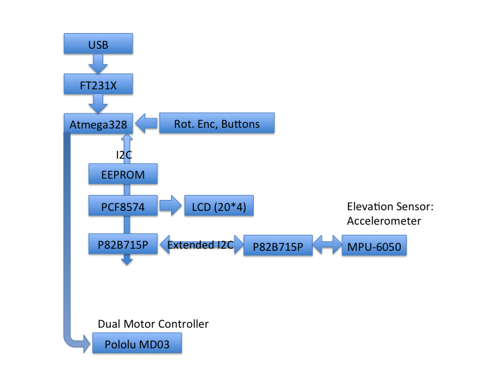
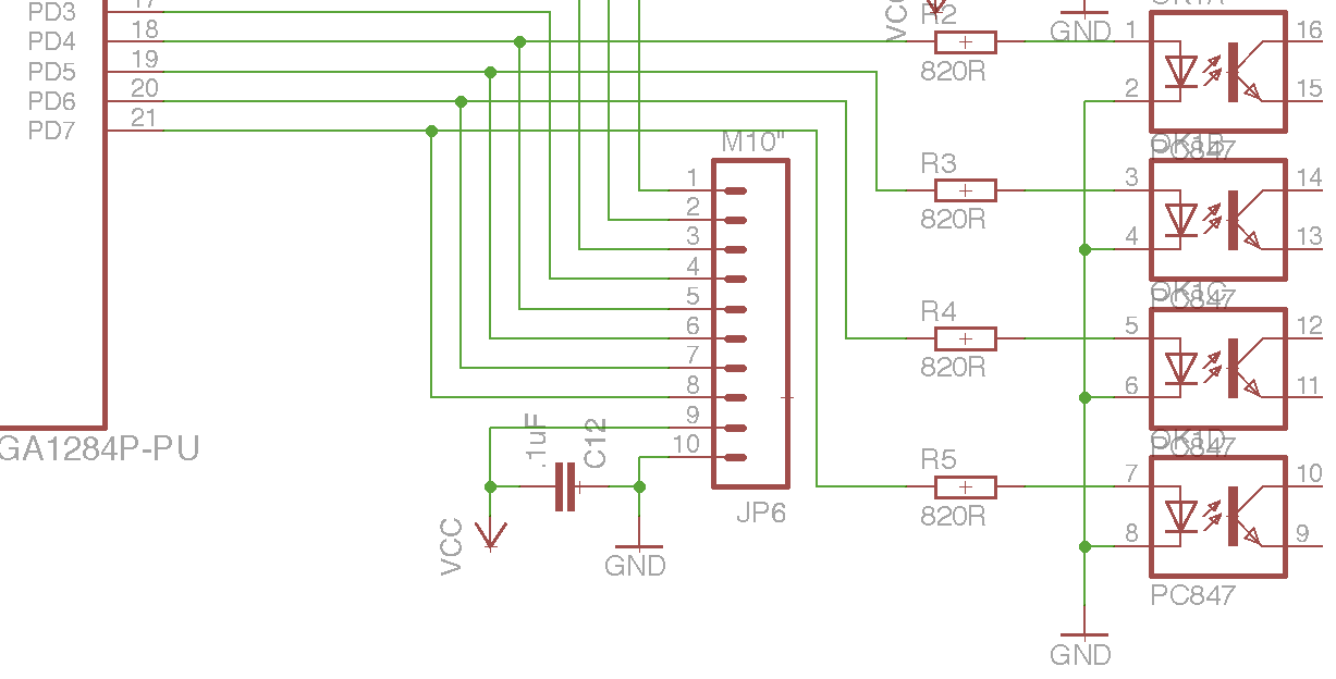
In order to control the 24v20 I am planning to use the PWM ports of an atmega1284P to control PWM, DIR and RESET of the motor controller. FF1 and FF2 should either go to LEDs on the case for manual intervention or (probably better) to the microcontroller and cause an immediate low on PWM and RESET.
As the motor controller (24 V) and the uC (5V) have independent power supplies, is it ok to just tie the grounds together or should the motor controller be attached via an optocoupler (LTV847) and a second one for bringing the fault flags to the uC?
The plan at the moment is to put the uC, Motor controller and a 24V Power supply in a metal project box, and grounding everything. The whole thing might also be connected to a computer via USB if one wants to run an observation program.
As my professional background is not in electronics, I’d be happy for some pointers; not wanting to fry either the 24v20 or the atmega…
Thank you very much.