We are building an ROV. We want to control motors through serial from an Arduino. To set the serial we want to use a potentiometer (joystick in the future). The data from the potentiometer is being sent correctly to the Arduino because we see the numbers changing in the serial monitor. Unfortunately, the data sent to the motor control device (jrk 21v3) does not read the serial input at all. Here is the code we are using. We think the problem is that the motor control is not reading the serial data correctly.
[code]
int potPin = 0; // analog pin used to connect the potentiometer
int val; // variable to read the value from the analog pin
int motorPin = 16; // TX for motor
int motorPinRX = 17;
// the setup routine runs once when you press reset:
void setup() {
// initialize serial communication at 9600 bits per second:
Serial.begin(9600);
pinMode(motorPin, OUTPUT);
pinMode(potPin, INPUT);
}
// the loop routine runs over and over again forever:
void loop() {
// read the input on analog pin 0:
int sensorValue = analogRead(A0);
val = analogRead(potPin); // reads the value of the potentiometer (value between 0 and 1023)
val = map(val, 1, 1023, 0, 4095); // scale it to use it with the servo (value between 0 and 180)
float voltage = val * (5.0 / 1023.0);//voltage readings
if (val >= 0)
{
Serial.println(val);
// Serial.println(voltage);
digitalWrite(motorPin, val);
}
delay(50); // delay in between reads for stability
}[/code]
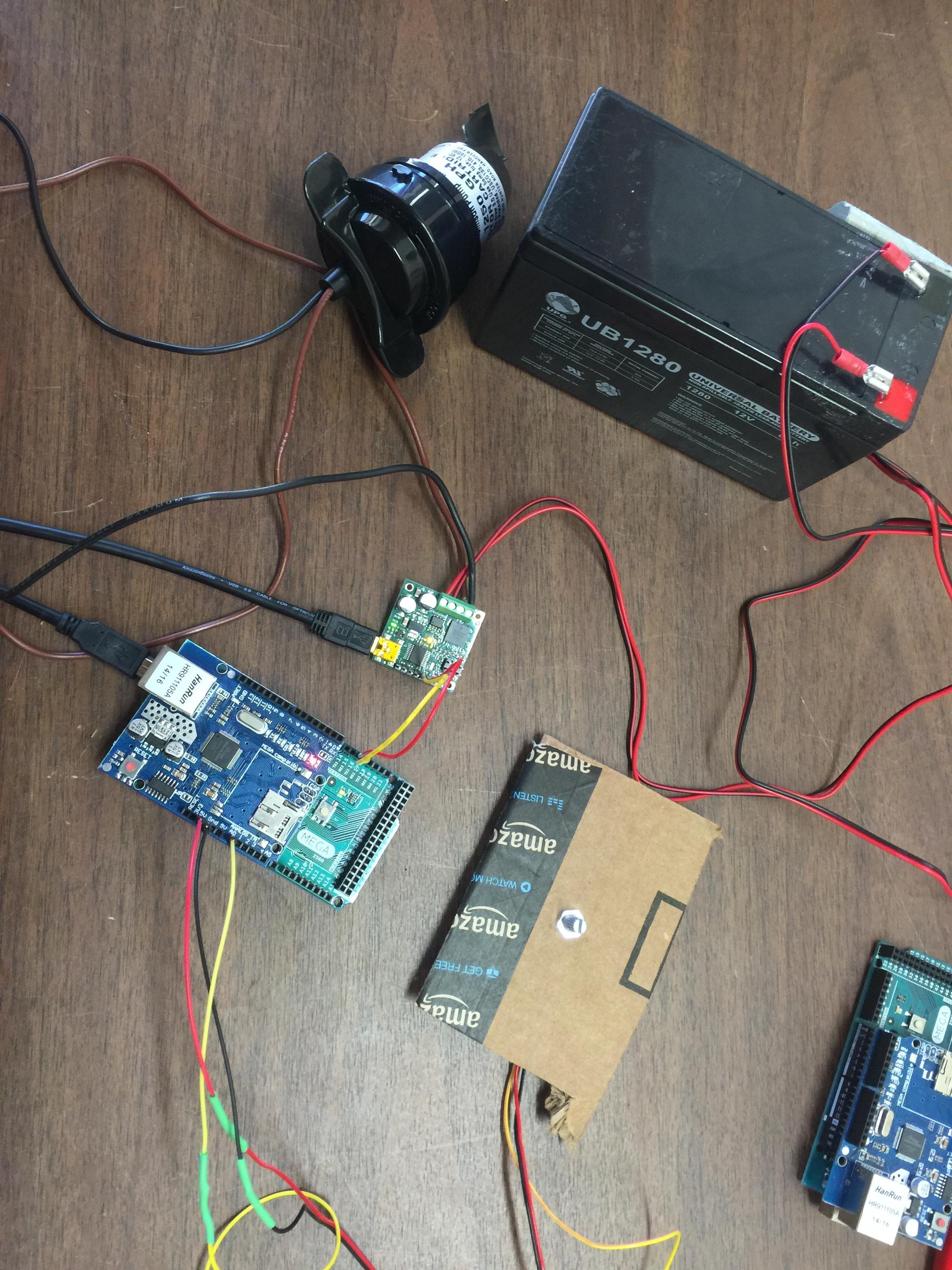
Here’s how we have all the hardware setup:
Is that code the one you are using to send the serial commands to the jrk? I do not see any of the serial commands being sent in that sketch. It looks like it just prints out the remapped value. I am not sure what you expect to happen with the “digitalWrite(motorPin, val);” line of code. To send serial commands to set the target on the jrk, you will need to follow the serial protocols outlined in the Motor Control Commands section of the jrk user’s guide. If you are new to sending serial bytes, you might find the Set Target Low Resolution Forward command (with the compact protocol) easiest to use. For this command, you must first send the command byte (0xE1), followed by the magnitude (which is defined in the section I linked to above). If you try sending the correct commands and still have problems, you can post your updated sketch, and I would be glad to take a look.
By the way, the jrk has an analog input mode; is there a reason you do not want to connect the potentiometer directly to the jrk?
The reason we do not want to use an analog signal is it will be running down a 60 ft tether near a power wire. Shielding does not work in our application. We are using the Arduino to use serial to avoid this.
Honestly, we are very new to all of this digital stuff. We completely understand analog, but have found the benefits of digital to be strong enough to switch.
We don’t really know how to send serial commands. We thought we were doing that with the digitalWrite line of code. We are just having trouble grasping the concept I think.
TTL serial uses digital signals, but it is different from digitalWrite(). You can find more information about using serial signals with Arduino on Arduino’s “Serial” reference page. In this case, you will want to use the Serial.write() function to send the command bytes that correspond to the jrk’s serial protocol (see the Motor Control Commands section of the jrk user’s guide I linked to in my previous response).
The snippet of example C code shown in the “Set Target High Resolution” command description (found in the Motor Control Commands section) shows how to get the correct serial bytes to send. The code you posted is already mapping the analog input to 0-4095, so you can use your “val” variable in place of the “target” variable shown in that example. Then you would need to send those serial bytes with Serial.write(). If you try updating your code to use serial and continue to have problems, you can post your new code and I’d be glad to take a look.
We must be doing something wrong. Here’s our new code, and we still are not seeing any input on the Pololu utility.
[code]#include <SoftwareSerial.h>
SoftwareSerial mySerial(19,18); // RX, TX, plug your control line into pin 8 and connect it to the RX pin on the JRK21v3
int serialBytes [10];
int potPin = 0; // analog pin used to connect the potentiometer
int val; // variable to read the value from the analog pin
int motorPin = 18; // TX for motor
int motorPinRX = 19;
// the setup routine runs once when you press reset:
void setup() {
// initialize serial communication at 9600 bits per second:
Serial.begin(9600);
mySerial.begin(4800);
}
// the loop routine runs over and over again forever:
void loop() {
// read the input on analog pin 0:
int sensorValue = analogRead(A0);
// print out the value you read:
val = analogRead(potPin); // reads the value of the potentiometer (value between 0 and 1023)
val = map(val, 1, 1023, 0, 4095); // sca
serialBytes[0] = 0xC0 + (val & 0x1F); // Command byte holds the lower 5 bits of target.
serialBytes[1] = (val >> 5) & 0x7F;
// Serial.println(val);
// Serial.println(voltage);le it to use it with the servo (value between 0 and 180)
// float voltage = val * (5.0 / 1023.0);
mySerial.write(serialBytes[0]);
mySerial.write(serialBytes[1]);
Serial.print(serialBytes[0]);
Serial.println(serialBytes[1]);
Serial.println(val);
delay(50); // delay in between reads for stability
}[/code]
Your serialBytes values look correct. What serial interface setting do you have the jrk set to? If it is configured for UART, detect baud rate, you will need to send the 0xAA byte first so it can detect the baud rate. If it is set to UART, fixed baud rate, you should make sure it matches the baud rate specified by your code (e.g. 4800 in the code you included in your last post). You might also double check that the serial connections are made correctly (e.g. the Arduino pin you designate as TX in your code should be connected to the jrk controller’s RX pin, and the pin you choose for RX should be connected to the jrk controller’s TX pin).
By the way, I noticed you have RX for your software serial defined as pin 19. It looks like you are using an Arduino Mega, which does not support change interrupts on pin 19. You can see a list of compatible pins on the SoftwareSerial Library Arduino Reference page.
If you change those things and it is still not working, can you include your updated code and jrk settings file in your next post? You can save your jrk settings file by selecting the “Save Settings File…” option within the “File” drop-down menu within the Jrk Configuration Utility.
[code]#include <SoftwareSerial.h>
SoftwareSerial mySerial(19,18); // RX, TX, plug your control line into pin 8 and connect it to the RX pin on the JRK21v3
int serialBytes [10];
int potPin = 0; // analog pin used to connect the potentiometer
int val; // variable to read the value from the analog pin
int motorPin = 18; // TX for motor
int motorPinRX = 19;
char buffer[4];
//int val2;
// the setup routine runs once when you press reset:
void setup() {
// initialize serial communication at 9600 bits per second:
Serial.begin(9600);
mySerial.begin(9600);
}
// the loop routine runs over and over again forever:
void loop() {
// read the input on analog pin 0:
int sensorValue = analogRead(A0);
// print out the value you read:
val = analogRead(potPin); // reads the value of the potentiometer (value between 0 and 1023)
val = map(val, 1, 1023, 0, 4095); // sca
//buffer[val] = Serial.read();
//val2 = (buffer[0]-48)*1000+(buffer[1]-48)*100+(buffer[2]-48)*10+(buffer[3]-48);
serialBytes[0] = 0xC0 + (val & 0x1F); // Command byte holds the lower 5 bits of target.
serialBytes[1] = (val >> 5) & 0x7F;
// Serial.println(val);
// Serial.println(voltage);le it to use it with the servo (value between 0 and 180)
// float voltage = val * (5.0 / 1023.0);
mySerial.write(serialBytes[0,1]);
// mySerial.write(serialBytes[1]);
// Serial.print(serialBytes[0]);
// Serial.println(serialBytes[1]);
// Serial.println(val);
delay(50); // delay in between reads for stability
}[/code]
Okay, so here is our new code. We’re not seeing any input on the Pololu program. We’re not getting errors in the program either, however. Just no indication it is reading the potentiometer.
I was able to load your settings onto a jrk controller here, and tried your code without modification, and it did not work; however, after I modified the mySerial.write() lines slightly, it worked fine. To demonstrate the change I made, I simplified your code by taking out the unnecessary and commented out code:
[code] #include <SoftwareSerial.h>
int motorPin = 18; // TX for motor
int motorPinRX = 19; // RX pin. Note that pin 19 on the Arduino Mega is not compatible
int serialBytes [2];
int potPin = 0; // analog pin used to connect the potentiometer
int val; // variable to read the value from the analog pin
SoftwareSerial mySerial(motorPinRX, motorPin);
void setup() {
mySerial.begin(9600);
}
void loop() {
val = analogRead(potPin); // reads the value of the potentiometer (value between 0 and 1023)
val = map(val, 1, 1023, 0, 4095); // scale to the appropriate target values
delay(50); // delay in between reads for stability
}[/code]
Please note, as I mentioned in the comments of this code and my previous post, pin 19 will not work for the RX pin when using SoftwareSerial. You should change it to one of the pins specified as compatible with the Arduino Mega on the SoftwareSerial Library reference page on Arduino’s website.
Sorry about the confusion. I forgot to mention that you should also uncheck the “Enable CRC” option in the “Input” tab of the Jrk Configuration Utility since the code is not sending any of the necessary bytes for the Cyclic Redundancy Check. You can see more about this in the “Cyclic Redundancy Check (CRC) Error Detection” section of he jrk user’s guide. With CRC disabled, the serial protocol error should go away.
We figured it out. Here’s the code that worked for us (for anyone that might have a similar problem):
[code]/*
AnalogToSerial
Reads an analog input on pin 0, outputs to TX.
*/ #include <SoftwareSerial.h>
SoftwareSerial mySerial(10,18); // RX, TX, plug your control line into pin 16 and connect it to the RX pin on the JRK21v3
//SoftwareSerial mySerial(11,10); // for UNO RX, TX, plug your control line into pin 16 and connect it to the RX pin on the JRK21v3
int serialBytes [10];
int potPin = 0; // analog pin used to connect the potentiometer
int val; // variable to read the value from the analog pin
char buffer[4];
void setup() {
Serial.begin(9600);
mySerial.begin(9600);
pinMode(10, INPUT);
pinMode(18,OUTPUT);
//pinMode(11, INPUT); // for UNO
//pinMode(10,OUTPUT); // for UNO
}
void loop() {
val = analogRead(potPin); // reads the value of the potentiometer (value between 0 and 1023)
val = map(val, 0, 1023, 0, 4095); // scales value to desired numbers
Serial.print(val);
Serial.print (" ");
// compact hi res mode
serialBytes[0] = 0xC0 + (val & 0x1F); //this line and the one below
serialBytes[1] = (val >> 5) & 0x7F; //are the bytes we are sending
//we are using compact protocol for setting target to low resolution https://www.pololu.com/docs/0J38/4.e
mySerial.write(0xAA);
mySerial.write(serialBytes[0]); //bytes that are sent
mySerial.write(serialBytes[1]); //bytes that are sent

Serial.print(serialBytes[0]); //numbers on serial monitor
Serial.print (" ");
Serial.println(serialBytes[1]); //numbers on serial monitor
delay(50); // delay in between reads for stability
}[/code]