Hello, hope someone can help solve this problem. I’m working on a Obstacle Avoiding Robot project and I’m using these magnetic encoders https://nodna.de/Motor-Encoder_1 .
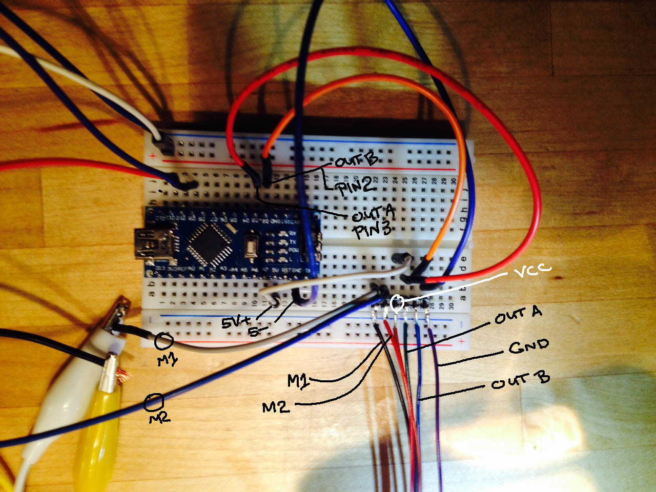
This is now I have it connected. The encoder is being powered by the Arduino’s 5v pin. M1, M2 are connected to a motor driver. OUT B = D2, OUT A = D3. I’ve tried testing both of these as the Interrupt.
I’m using this bit of code to test the encoder:
// sample arduino code for getting relative speed from an encoder
// this code will print the # of encoder ticks each 1/2 second
volatile int counter = 0;

void setup(){
       attachInterrupt(0, count, RISING);
       serial.begin(19200);
}

void loop(){
       counter=0;
       delay(500);
       serial.print(counter);
       serial.print("\n");
}

void count(){
       counter++;
}
I would expect to see the counter increase each time the loop runs. I’m only getting a value of “0” each time. I’ve also tried changing the Interrupt event to HIGH, CHANGE; FALLING, LOW, also the same. https://forum.pololu.com:/uploads/default/original/2X/8/87dc41712bb81916f71a7025b73f764286161745.mov
If I test the encoder manually with a voltmeter I do see some changes in the readings.
Thanks!
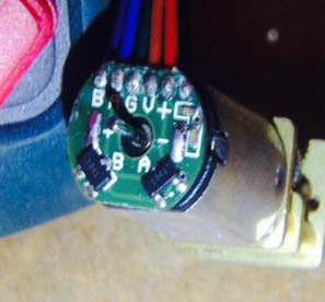
From your video, it looks like you might be using one of our Micro Metal Gearmotors with Extended Motor Shafts with one of our Magnetic Encoder Pair Kits. If so, the magnetic encoder board should already have 10K pull up resistors connected to OUTA and OUTB, which is shown under the “Schematic diagram” section on the magnetic encoder product pages. Can you post close-up pictures of the encoder board you are using clearly showing the components on it? Can you also diconnect OUTA and OUTB from your circuit and try measuring the resistance between them and ground with a multimeter?
I’m still having problems with the encoder. To answer your questions here are a few links.
This is a link I got from noDNA showing the Schematic diagram and wire coding. The wiring code seems to be correct. https://nodna.de/media/noDNA/Magnetic-Encoders-12CPR.pdf
This link is to noDNA product page showing the encoder, but it doesn’t seem to match up with the first link Schematic or wire coding.
Multimeter reading are 3.0mega ohms for B-out, 2.88 mega ohms A-out. Here is a close-up of the encoder.
After adding the 10K pull-up resistors to both OUT A/B it seems to be reading OUT A, but still not OUT B. I really need it to be able to read both channels. Thanks for your help.
The encoder board in the picture does not look like one of our magnetic encoder boards.
I did a quick search on the noDNA website and found some micro metal gearmotors with 12 CPR encoders that they manufacture, which look similar to what you are using. Their product pages contain the same datasheet you linked under the “Technical Data (at 6VDC)” section. You should note that the datasheet shows two versions of the encoder board, where one version of the board only has one OUT channel. It is possible that you confused our magnetic encoder board with another on the noDNA website?
I recommend contacting noDNA to determine which version of their encoder board you have.
Thanks Amanda,
I’ve checked with noDNA and you’re right. The 12 CPR encoder from noDNA don’t have 10k resistors. Adding the resistors got it to work. Also ordered these https://nodna.de/Magnetic-Encoder-Pair-Kit-for-Micro-Metal-Gearmotors-12-CPR-27-18V and they came in today. These are from Pololu, added them to my project works great!!