I think I have destroyed 6 different A4988/A4983 chips, but I don’t know what I might be doing that is causing this.
I was hoping for two things (1) a way to confirm that the chips are dead; and (2) a hint as to what I am doing wrong.
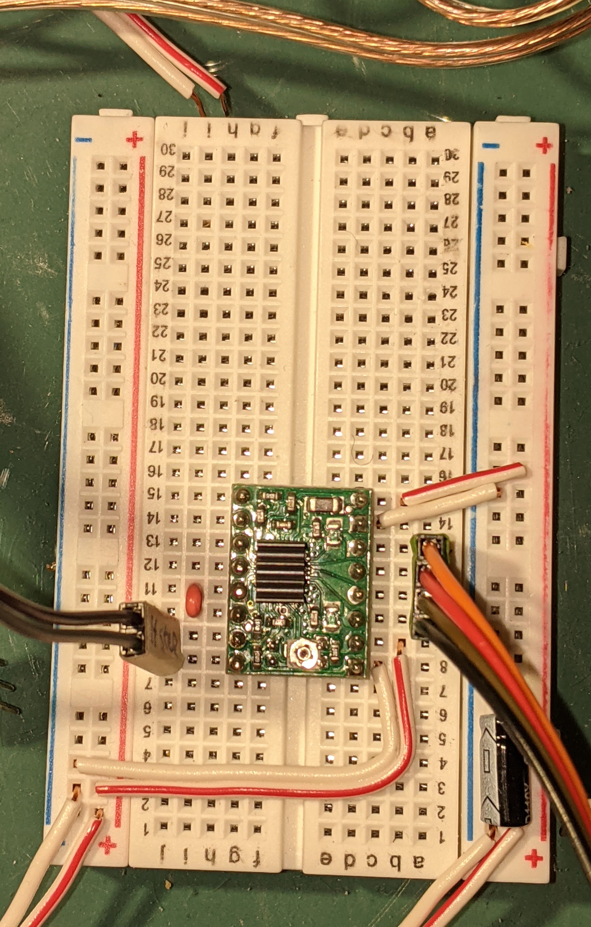
The picture below is what I am currently testing. The power on the right is 12v and the power on the left is 5v. STEP and DIR is run by an arduino and 1a/1b/2a/2b is connected to an NC17. I have had this working early on with the connections and code shown below, but now the motors do not respond.
I have read that disconnecting the motor connections while power is on will damage the chip. Before I read that I recall doing exactly that on two of the a4988’s. But not all 6.
I have also read that if 5v and 12v power is supplied to the chip I should be able to measure 12v across 1a/1b or 2a/2b. I can only read 0v.
This code is from A4988 Stepper Motor Driver with Arduino Tutorial (4 Examples) about midway through the article.
/*Example sketch to control a stepper motor with A4988 stepper motor driver and Arduino without a library. More info: https://www.makerguides.com */

// Define stepper motor connections and steps per revolution:
#define dirPin 2
#define stepPin 3
#define stepsPerRevolution 200

void setup() {
  // Declare pins as output:
  pinMode(stepPin, OUTPUT);
  pinMode(dirPin, OUTPUT);
}

void loop() {
  // Set the spinning direction clockwise:
  digitalWrite(dirPin, HIGH);

  // Spin the stepper motor 1 revolution slowly:
  for (int i = 0; i < stepsPerRevolution; i++) {
    // These four lines result in 1 step:
    digitalWrite(stepPin, HIGH);
    delayMicroseconds(2000);
    digitalWrite(stepPin, LOW);
    delayMicroseconds(2000);
  }

  delay(1000);

  // Set the spinning direction counterclockwise:
  digitalWrite(dirPin, LOW);

  // Spin the stepper motor 1 revolution quickly:
  for (int i = 0; i < stepsPerRevolution; i++) {
    // These four lines result in 1 step:
    digitalWrite(stepPin, HIGH);
    delayMicroseconds(1000);
    digitalWrite(stepPin, LOW);
    delayMicroseconds(1000);
  }

  delay(1000);

  // Set the spinning direction clockwise:
  digitalWrite(dirPin, HIGH);

  // Spin the stepper motor 5 revolutions fast:
  for (int i = 0; i < 5 * stepsPerRevolution; i++) {
    // These four lines result in 1 step:
    digitalWrite(stepPin, HIGH);
    delayMicroseconds(500);
    digitalWrite(stepPin, LOW);
    delayMicroseconds(500);
  }

  delay(1000);

  // Set the spinning direction counterclockwise:
  digitalWrite(dirPin, LOW);

  //Spin the stepper motor 5 revolutions fast:
  for (int i = 0; i < 5 * stepsPerRevolution; i++) {
    // These four lines result in 1 step:
    digitalWrite(stepPin, HIGH);
    delayMicroseconds(500);
    digitalWrite(stepPin, LOW);
    delayMicroseconds(500);
  }

  delay(1000);
}
Hello.
What stepper motor, power supplies, and heat sinks are you using with your drivers? Ideally, please post datasheets for them or links to where you got them. What are you setting VREF to when you test your drivers?
Also, can you post some pictures showing the entire setup that show all of your connections (not just the breadboard) and some pictures of the top and bottom sides of all 6 of your drivers?
By the way, we have not made stepper motor drivers using the A4983 stepper motor driver for several years, so if you got your drivers from us recently, then they are almost certainly A4988s.
- Patrick
- I have 4 NC17 stepper motors from when I built a Mendelmax 3d printer in 2011, purchased from http://lulzbot.com.
- The power supply is a brick from an old Buffalo router, rated for 12v & 1.5A output.
- The heat sinks came with the stepper motors.
- 2 of the A4988 were also purchased in 2011 for the 3d printer from lulzbot.com. 4 of the drivers are BIQU A4988 compatible, purchased in Nov through Amazon here.
VREF is set to 0.6V.
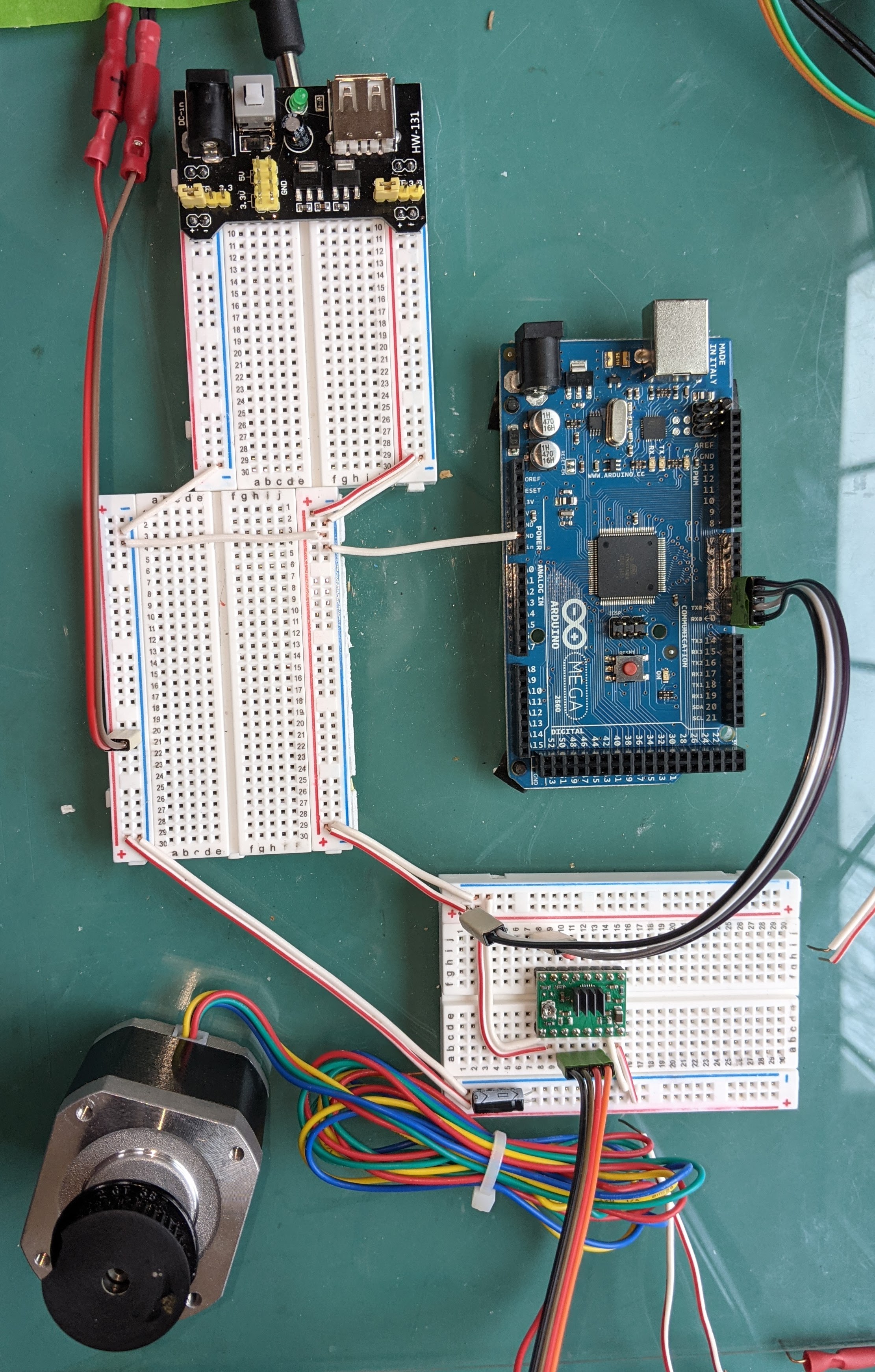
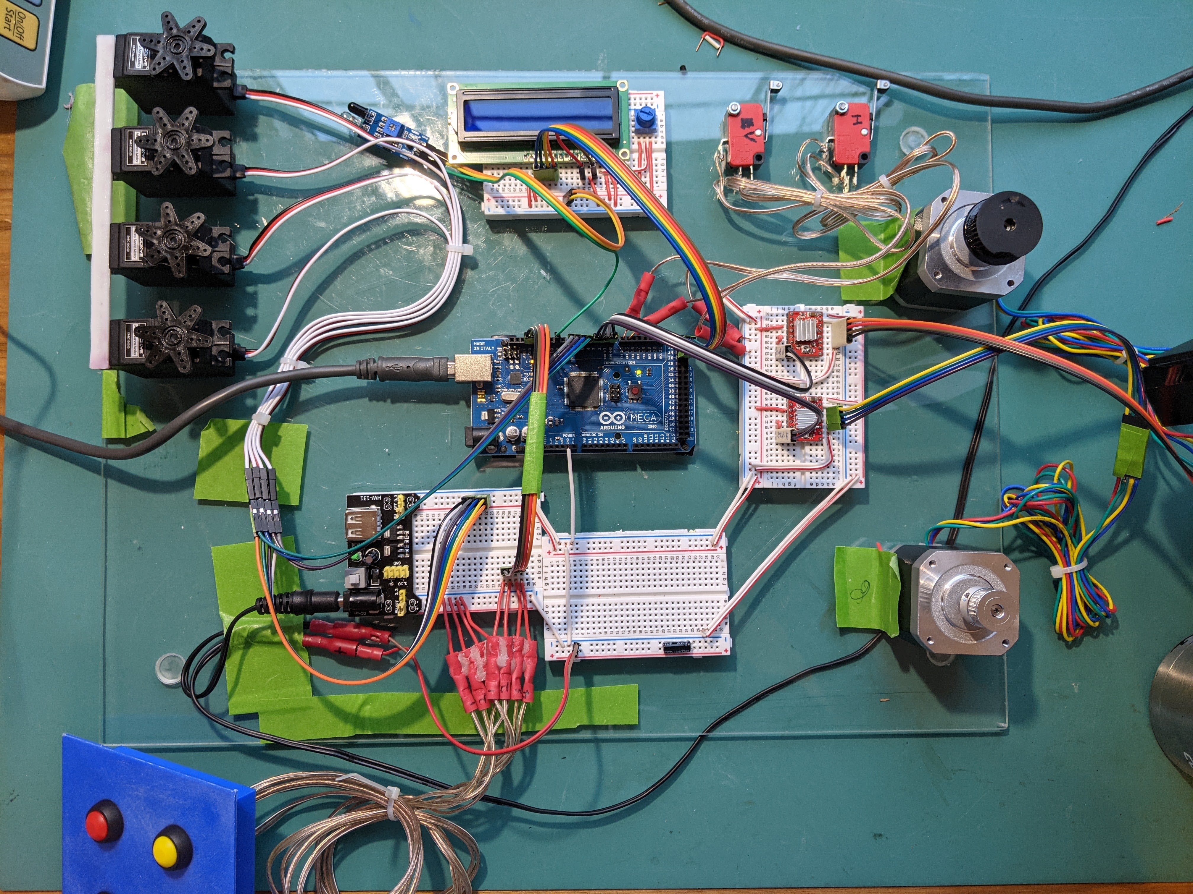
This first picture is what I am testing: a single subset of the project, as I described. The second picture is the entire logic of the project, ostensibly complete.
Assuming the “why” is not easy, is there a good answer for confirming that the chips are dead?
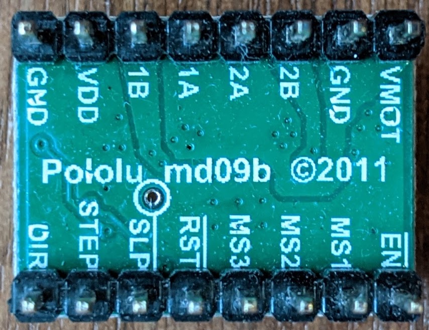
We never manufactured A4988 or A4983 carriers with red PCBs, so those four drivers are not ours, so we cannot offer any specific troubleshooting advice for them since they are likely different from ours.
The green boards do look like ours, but to make sure can you post a picture of the back of the green boards showing the silkscreen labels? Do you remember if those drivers ever worked for you? Given their age, can you also try to remove the heat sinks so you can read the label on the IC to determine whether they are A4983 or A4988 drivers?
Unfortunately, there is not some easy way to determine whether or not a driver is damaged other than just testing it in a minimal setup following the minimal wiring diagram on the A4988 product page. The first picture in your last post looks to be close to that, but I suggest removing the extra breadboards to minimize the total number of connections and setting a more conservative current limit (for example, try setting VREF to 0.3V). You might also try a different position in the breadboard in case some of the rails are damaged. If your drivers do not work in that setup, try to implement a minimal setup without using breadboards. (Breadboards are not designed to handle the high currents.)
We noticed that you ordered more replacement drivers from us, so if you continue to get no signs of life when you test your drivers in that setup, then I suggest waiting until those arrive and testing them the same way.
By the way, this might be challenging given how old your parts are, but if possible can you try to figure out exactly what stepper motors you have or a datasheet for them? (I found two stepper motors on Lulzbot’s website, but they appear to have different specifications from each other.)
- Patrick
I am sure you never made a4988 with red PCBs, which is why I ordered new ones.
I actually have four of the pololu chips pictured here, but just haven’t pulled two of them from the controller board on the printer. All four worked up until I took the Mendelmax apart last year when I bought a new printer.
I’ll try the new a4988’s and a lower VREF. I am surprised that there is not some diagnostic that manufacturing does to confirm parts, even if only on a random subset.
Thanks for the detailed answers. I think you are a great value to this forum.
Todd
Thanks for posting the picture. That is definitely our board, so if your other green boards also look like that then they are all ours too. Were you able to determine which driver is on them? If possible, can you check if the old control board still works with the drivers you still have installed in it? Do the drivers that are not working in your breadboard setup work if you put them back in the control board?
Just to clarify, we test every carrier board that we make to fully check their functionality, but we use a testing fixture we specifically designed for that, so it would not be practical to recreate it.
- Patrick