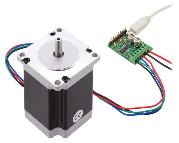
If you look at that image, some boards have B1 and B2 the otherway around than others. But the image is the same for everyone. I cannot comprehend this. As my motor 1477 comes with only same image but without mentions of B1 and B2. Can anyone give any meaning to this?
for reference, I’m using the black Tic board this time. Lasttime was green.
If someone can’t see the image it’s this page
Pololu - 4.2. Connecting the stepper motor and power supply
This leds me to believe
A1 Red
A2 Blue
B1 Green
B2 Black
If you look at Note 1 towards the end of this page on Instructables it walks through how to figure out which stepper wire needs to go where. It more or less boils down to testing a random order and if it doesn’t work, you swap some wires around until it works and then once it starts working, you might still need to perform a final swap if the direction of rotation isn’t to your liking. Just remember to disconnect power before performing any of these swaps or you could damage your driver.
The wire designations are arbitrary. The motor will run regardless of which you call B1 and B2. If the shaft rotation direction does not agree with the setting of the DIR pin, simply swap B1 and B2. Or swap A1 and A2. With the power off, as mentioned above.
2 Likes
Hello.
Jim is correct; when wiring a stepper motor, the important part is to determine which wires go to the same coil, and make sure those wires pair together with the driver’s outputs (i.e. the pair of wires for one coil should go to the A# pins and the pair for the other coil to the B# pins).
So, in your example, A1 and A2 are connected to red and blue respectively, and B1 and B2 are connected to green and black respectively. This is fine since red and blue on the #1477 stepper motor belong to one coil and green and black to the other. If you were to swap green and black so green goes to B2 and black goes to B1, it would still work fine, but the motor will turn in the opposite direction (so the direction that the Tic associates with “forward” and “reverse” would swap).
As far as that instructable article, I would not recommend randomly connecting the wires like it recommends. While it probably won’t damage anything (assuming nothing is powered while you’re changing the connections!), there is no guarantee, and if you do not have the documentation for your stepper motor that specifies which wires belong to the same coil, you can figure it out by using a multimeter to measure the resistance between the wires.
Brandon
1 Like
It’s just that in this version of installation there’s a multitude of other things that might go wrong, too, like SPI channel difficulties. So it would be really helpful if Pololu motors game labeled with A1, A2, B1 and B2. And stop using A1OUT and B1OUT and whatever.
Which have nothing to do with how the motor leads or PCB pinouts are named.
It makes perfect sense for Pololu engineers to name PCB pinouts following the convention used by the manufacturer to name pins on the chip.
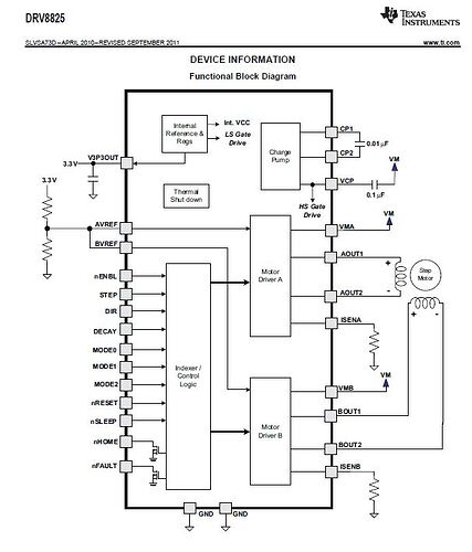
See this example for the DRV8825 from Texas Instruments, which use AOUT1, AOUT2, etc.
I understand. I just wish Pololu added B1/B2/A1/A2 to their motors.
What I meant with the multitude of other things, was that swapping B1/B2 isn’t a lucrative option when the cabling might be right but SPI connection broken. So having a direct instructions - this color goes to B1, is in my opinion better.


