I am using a 18v17 motor driver to drive 12V heating pads. Each one draws about 3.8A when I supply them with 40% duty cycle pwm, and I had three plugged into the output of the driver, so it should have been drawing about 12A. I also had the CS pin printing to serial, which showed about 14A current draw. After about 3 minutes of running this, the onboard capacitor started smelling really bad and then blew up. I also had a 330 uF 25V capacitor on the (+)(-) leads. Is this because I need a bigger capacitor or is there a different problem with my setup?
While I’m here, I also wanted to ask about the CS output. It was giving a really large oscillation, from about 0 to a voltage proportional to the current. Is this normal, and how do I get good data from it?
Those heating pads are probably mostly resistive, meaning the current is not averaging out over your PWM cycle and instead getting used in very high peaks, which is likely causing your supply to have huge fluctuations that the capacitor is trying to smooth out. A lot more capacitance could help, but you might just move the failure point somewhere else.
I recommend looking at things with an oscilloscope. If you post pictures of your setup and more details about your supply, load, and PWM frequency, I would be happy to take a look for any other issues.
The CS signal is only valid during the high portion of the PWM output. During the low portion reading 0V is expected. You could try averaging CS readings and then dividing them by (1- duty cycle) or synchronizing your CS readings with the PWM high time.
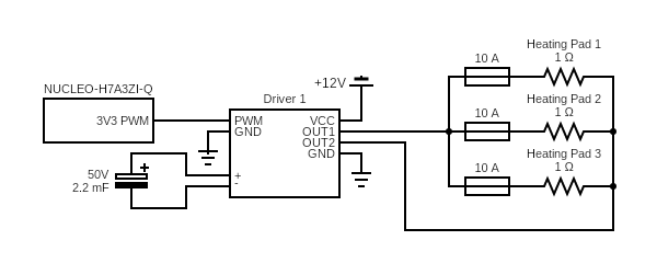
Thanks so much for the reply, that is super helpful. My setup is this:
However when the onboard capacitor broke I only had a 330 uF 25V capacitor installed and had no fuses on the heating pads.
This is the 12V power supply I am using, it is rated up to 30A. These are the heat pads, rated as 12V, 150W, 1Ohm.
I am using 40kHz for the PWM to reduce rattling of hardware in the power supply, but have run it as high as 80kHz and low as 25kHz.
Thanks for the tip about the CS pin, I could probably have an interrupt handler read current when it detects a rising edge of the PWM right?
Thanks again for the help!
Lauren
Update: I scoped the output of the motor driver and it’s a perfect 12V square wave (with duty cycle corresponding to input pwm). Is this where I should expect some type of capacitor smoothing, or do I need to scope the capacitor itself? If there is a circuit diagram of the driver that would be super helpful, I can’t find one on the website.
You should look at the voltage directly across the capacitor. If you have the option, a much lower PWM frequency (like hundreds of Hz) should help since the capacitor might get a chance to fully charge. We do not release the schematics for this driver, but if you have a specific question I might be able to help.