
I am moving forward with my testing on the TB67S128FTG. I am just trying to learn how it works and its features. In doing so I may have broken it but I am not sure. I calculated my Vref to be 1.4 (includes a 10% reduction). After running for about 10 minutes the motor stopped. LO0 was reading 5v and LO1 was reading 2.5v. Based on the datasheet this is a motor open load error? I have tried to clearing the error by resetting VM and GND as well as STANDY to LOW but it isnt resetting the internal MOSFET. Any ideas on whats going on? Is my board toast or does it still have a chance? Thanks in advance for any help!
A VREF of 1.4V would put the current limit just above the 2.1 A per phase we expect the TB67S128FTG to be able to handle continuously without additional cooling, so you should probably reduce that a little bit. What motor and power supply are you using? A measurement of 2.5V on LO1 is strange; how are you measuring those pins? Could you post pictures showing all of your connections (including any connections you made to read those pins)?
Also, I noticed in your other post, you mentioned that you were connecting 3.3V to the IOREF pin; did you switch that to 5V in your current setup?
Brandon
Ill post some pictures of how I am measuring the voltages…one second.
This is the motor:
I have my PEVONO PSU set to 12.10.
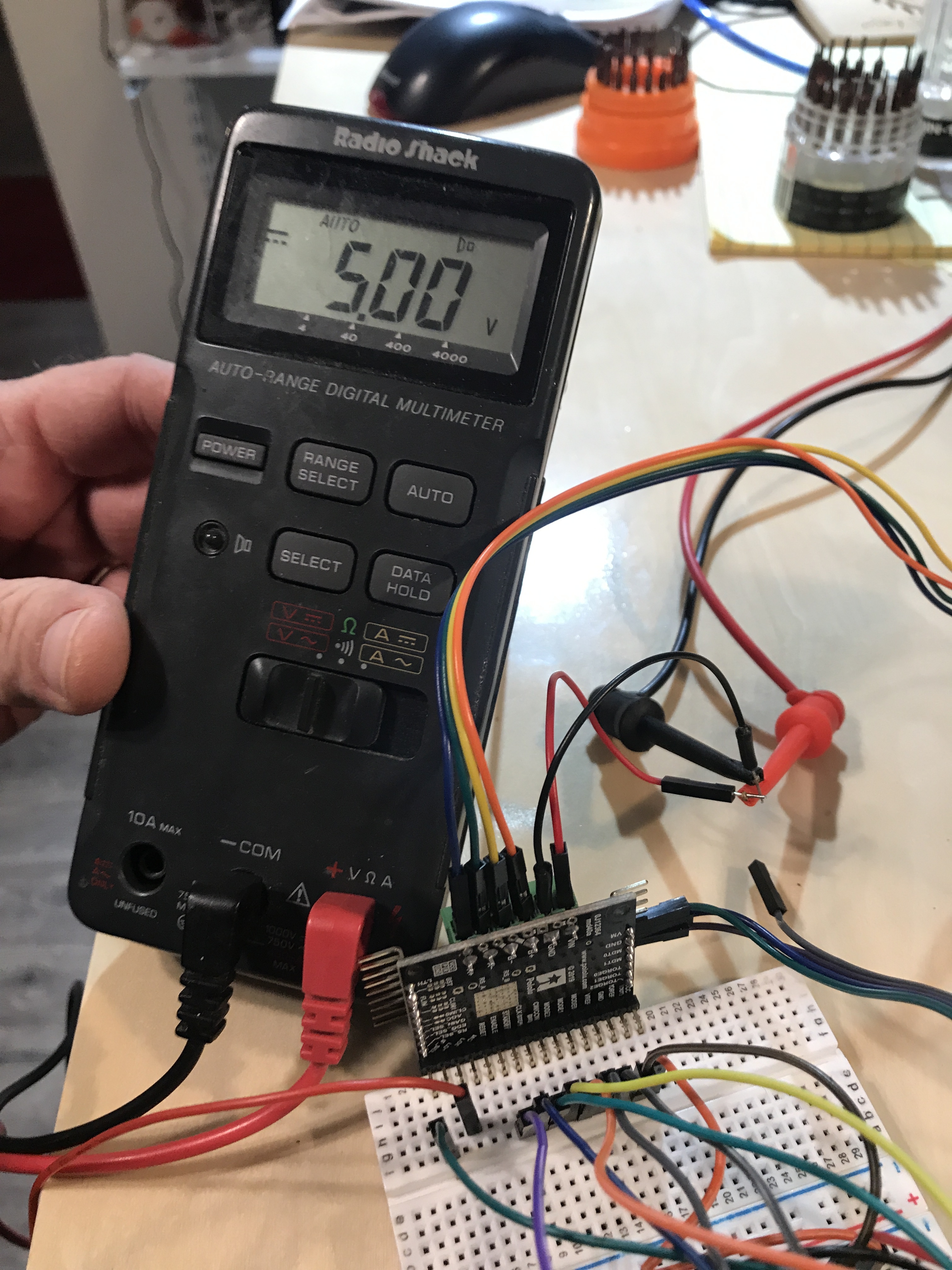
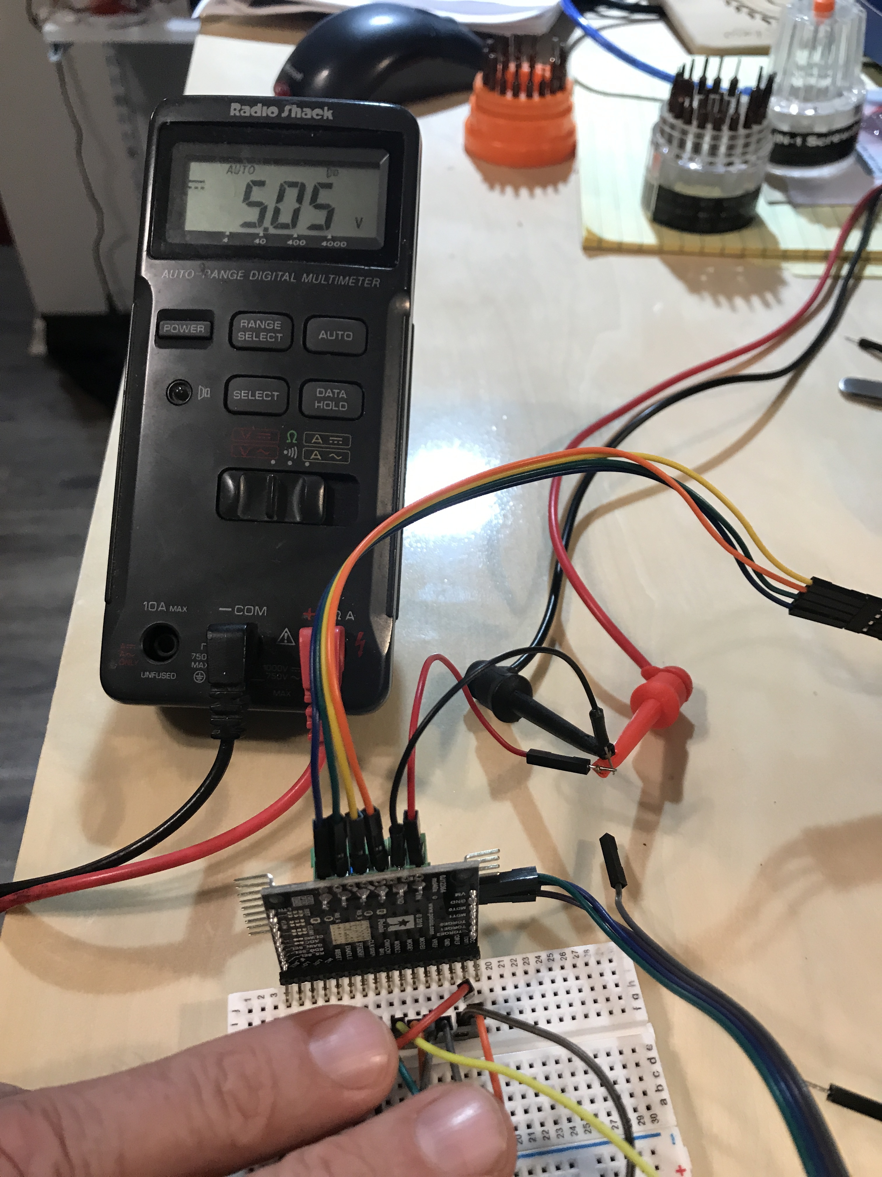
I have my meter GND connected to the GND rail for the board and Arduino
See pictures…I am getting 5v from LO0 and 2.5v from LO1. And I just noticed after connecting LO1 before powering with 5v that voltage on LO1 was 4.1 at power up… but it started dropping and eventually stopped at 2.5volts…hope this makes sense
Yes…I switch to 5v from the Arduino just to see if that would make a difference…but it did not.

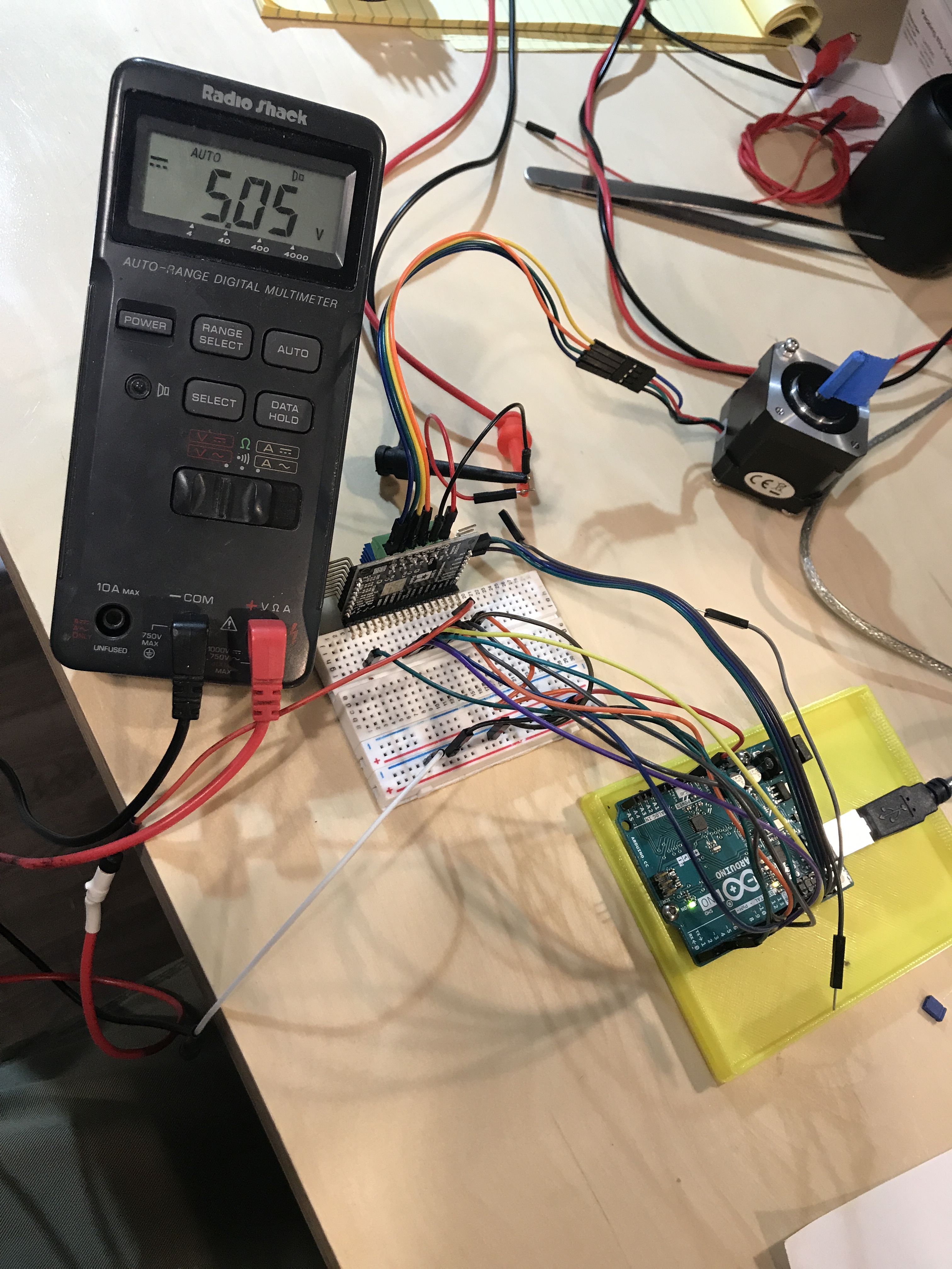
Thank you for the additional information. It is hard to make out all of the connections in your pictures, but I did not notice anything obviously wrong with them. I noticed in your last picture that it kind of looks like something might be mounted to the top-side of your TB67S128FTG; there seem to be some kind of blue-ish fins visible. Is that some kind of heat sink you added? It might be possible that it is shorting something on the board.
As I mentioned before, the ~2.5V reading is strange, and it could indicate that the board was damaged in some way. Could you try simplifying the connections as much as you can to be sure that it isn’t something with your wiring that is causing the problem. If you connect it as shown in our minimum wiring diagram, do you get the same results? If you have an oscilloscope, you might try looking at the signals with that just in case they are changing faster than your multimeter can reliably measure.
Brandon
Yes the blue fin is a heat sync that was added after the LO1 error occurred. I’ll try the minimum wiring and report back here shortly
Should I remove the heat sync?
I have it hooked up with minimal wiring. The motor is running but the voltage on LO1 is 4.11 volts and its dropping…same as before. Once LO1 gets to ~2.6v the motor will stop.
Did you ever reduce the current limit as I suggested in my previous posts? It looks like the stepper motor you linked to is rated for 2A per phase, so you should set VREF to ~1.28V or less. If your VREF is still set higher than this, could you try it again with the minimal wiring diagram setup after reducing the current limit and seeing if you get the same results? If the motor stops again with the lower current limit, was the run time longer than the previous test? Also, if the motor stops, could you measure the LO0 pin at that point?
If you installed the heat sink after you started having the problem, then it is unlikely to be causing the problem; if it’s easy to uninstall, you could try it just in case.
Brandon
My Vref is set at .9v. There is no difference in the how long it runs…Once LO0 gets to ~2.5 volts the motor stops. The heat sink have been removed.
What do you think is wrong with my driver board?
Does LO0 voltage stay low when the motor is holding a position instead of stepping? I suspect LO0 might be oscillating. If you have access to an oscilloscope, could you try capturing LO0 when the motor is stepping? If you have a different motor, preferably one that draws less current, could you try and see if the driver works with that one?
– Jeremy
The voltage is actually dropping on LO1 not LO0…my apologies!
here is a video of the scope reading and motor state. I discovered tonight that the voltage on LO1 actually climbs back up to after sitting for awhile. However it does drop back to 2.5v eventually.

It is difficult to see the oscilloscope in the video. Could you post screen captures instead? When you disconnect the microcontroller from the driver and motor starts to move, what connections are you removing?
– Jeremy
I only removed 5v from IOREF
If removing 5V from IOREF starts the motor, I suspect something else in your setup might not be connected correctly. Could you post a picture or diagram that clearly shows all the connections between the TB67S128FTG driver board and your microcontroller? It looks like you are using an Arduino in your setup. If so, could you post your sketch?
The breakout board pulls LO1 to IOREF through a 100k resistor, so it is not unusual for LO1 to be at 0V when you disconnect your 5V from IOREF.
– Jeremy
The Arduino is connected via minimum wiring diagram specs per Brandon’s request above. I have decided to go with a TMC driver. We aren’t making any progress on this issue.
I am sorry you are still having issues with your TB67S128FTG driver. It seems like the board might still be functioning, so if you would like to revisit this in the future, you can post the information I requested above and I would be happy to continue troubleshooting with you.
– Jeremy