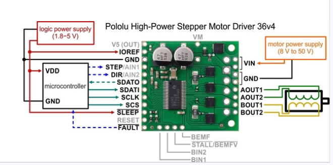
Hi everyone! I am using the Pololu High Power Stepper Motor Controller 36v4 and I cannot get more than 0.18A to my stepper motors. I created a pretty basic test system using an Arduino - I am just enabling the motors to hold a position with 2400mA in the code. However, it will only pull 0.18A from the power supply when the motors are enabled.
Does anyone know how to enable more power on these controllers?
Here is my test code (Arduino Due + pololu)
#include <SPI.h>
#include <HighPowerStepperDriver.h>

#define SERIAL_PORT Serial

// Driver 0 pins
const uint8_t sd0CSPin = 10;

bool enable_drivers_bool = true;

// Driver 0 object
HighPowerStepperDriver sd0;

//Debug Mode
bool debug_mode = true;

void setup()
{

  if(debug_mode){
      while (!Serial) {;}
      SERIAL_PORT.begin(115200); // Start the serial console
      SERIAL_PORT.println(F("Serial port connection starting."));
      }

  SPI.begin();
  sd0.setChipSelectPin(sd0CSPin);

  // Give the drivers some time to power up.
  delay(1);

  // Reset the drivers to their default settings and clear latched
  // status conditions.
  sd0.resetSettings();
  sd0.clearStatus();

  // Select auto mixed decay.  TI's DRV8711 documentation recommends this mode
  // for most applications, and we find that it usually works well.
  sd0.setDecayMode(HPSDDecayMode::AutoMixed);

  // Set the current limit. You should change the number here to an appropriate
  // value for your particular system.
  sd0.setCurrentMilliamps36v4(2400); //

  // Set the number of microsteps that correspond to one full step.
  sd0.setStepMode(HPSDStepMode::MicroStep1); //step mode


  // Enable the motor outputs.
  sd0.enableDriver();

  SERIAL_PORT.println("setup complete");
}

void loop()
{

  if(enable_drivers_bool){
  // Enable the motor outputs.
  sd0.enableDriver();
  enable_drivers_bool = false;
  SERIAL_PORT.println("Drivers Enabled");
  }
  else{
  // Disable the motor outputs.
  sd0.disableDriver();
  enable_drivers_bool = true;
  SERIAL_PORT.println("Drivers Disabled");
  }
  delay(8000);
}
Could you tell if the motors are actually getting energized when you run your program?
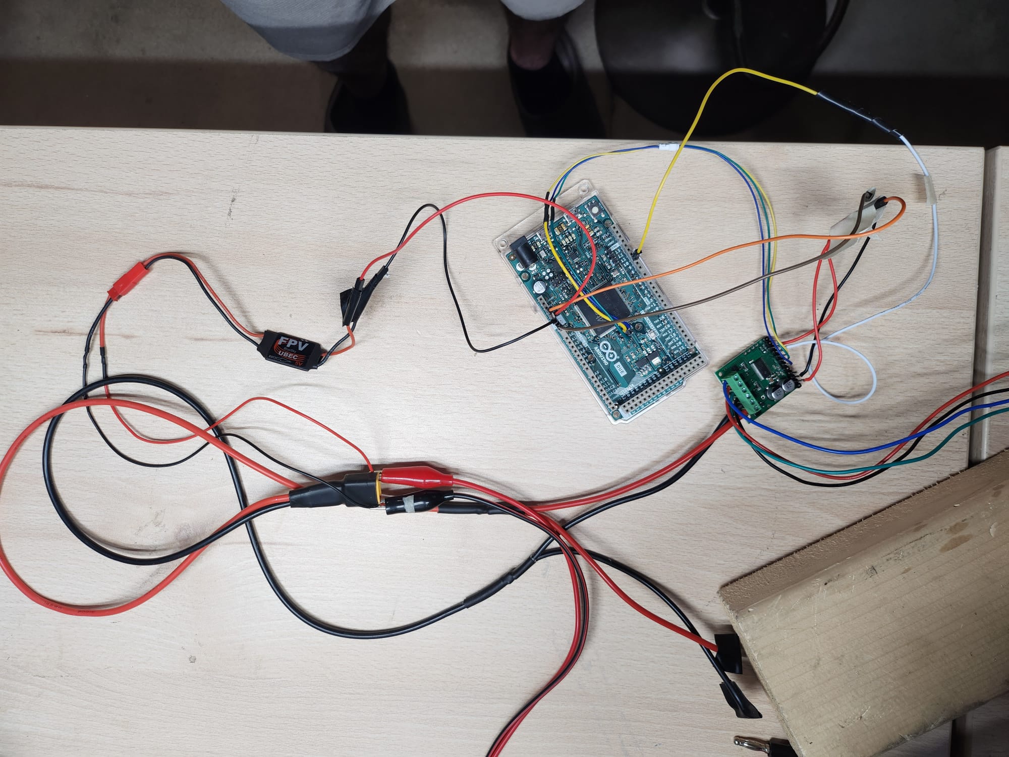
Could you post more details about your setup (e.g. what specific motors are you using and what power supply are you using)? Also, it sounds like you have multiple motors, but only one driver; could you post some pictures showing all of your connections (including how you are measuring the current)?
Thanks for the help! I am using one OYO stepper motor and here is a photo of my circuit (motor not shown, but you can see the wires going to the motor). The motors are getting energized. I confirmed the current from what the power supply reported, and also by measuring the voltage and resistance on the energized motor lines. The power supply is set to 12v btw, and powers the 5v BEC that powers the Arduino due.
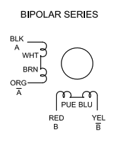
The stepper motor you linked to is an 8 lead stepper motor; could you clarify what you are doing with the other 4 leads? Are you connecting the motor in a bipolar series or bipolar parallel arrangement (both are described in the stepper motor’s datasheet)? Also, according to the datasheet and pictures from that product page, none of the wires should be green, but you have a green wire in your picture. Are you sure you are connecting the appropriate wires?
By the way, please note that the current draw shown on your power supply will not match the current draw through the coils. If you want to measure the current, you should measure the actual current through one coil of the stepper motor with something like a multimeter.
Also, it should be fine to power your Due with 12V through the VIN pin. Arduino’s page lists it as having a 7-12V recommended input voltage with a maximum input voltage of 16V.
yes the wires are correct, I had to extend them on the prototype we are working on and I didn’t have an orange wire (so I used green) and I also didn’t have a yellow wire so the blue wire in the photo is actually the yellow wire on the motor. They are connected in bipolar series, so the other 4 leads are shorted in pairs according to the data sheet.
I measured the current by measuring the resistance when turned off, then the voltage during operation, and divided resistance by voltage and it was pretty close to what the power supply reported. I also know the current is super low because I connected the motor directly to the power supply and increased to 3A and the holding force was a lot stronger. I also did use the multimeter method on measuring current and got a similar value.
The motor controller is working in that it will turn the motors as I command, but the holding force is just super weak. Could it maybe be something with the highpowerstepperdriver.h library?
Also, I just changed the 12V to go to the VIN rather than the BEC per your instructions. It had the same effect.
Could you try calling verifySettings() just before enableDriver() and check the returned value? Could you try using different decay mode settings to see if they make any difference?
Also, could you try testing a couple different current limit settings, such as 2800mA and 2000mA, and see if you get a corresponding change in the current draw?
Changing the current limit settings did not change the motor current.
I called the verifySettings() just before enableDriver() but where will I see the returned value?
I changed the decay mode to Slow, and this allowed more current into the system, I got it up to about 1000ma. However, changing the current limit settings still did not change the motor current. Even when I limited to 500ma it was still doing 1000ma
Slow and SlowIncMixedDec decay modes added a bit more torque, but the enabled motor at rest was only 0.6A and the current raised to 1000ma when I turned the motor. All other modes had an enabled motor at rest at 0.56A and 0.65A when turning the motor.
And sorry, the 0.18A was on the power supply, which is not the real coil current. My bad on that. The real coil current I’m getting was about 0.56A.
The current not changing when you adjust the current limit in your code is definitely strange. Could you try printing the result of verifySettings() to the Serial Monitor, at the end of setup(), before enabling the driver, like this?
If the settings read from the driver match the values in your code, it should return 1; if it returns 0, then something is going wrong with the configuration.
How many high-power stepper motor drivers do you have, and do you get the same behavior from all of them? Do you have a different motor you can try, or have you gotten this motor to work as expected with a different driver?
It is very odd for the current through the coil to be higher than the configured current limit; could you clarify how you measured the current in this test? Some pictures of how you had everything connected would probably be helpful.
The best way to get a better understanding of what is going on would be to use an oscilloscope current probe, which is unfortunately a pretty specialized piece of equipment. Would you happen to have access to something like that?
I have four of these drivers and they all have the same behavior. I also have two different motors, both have this same issue. Basically over the last month we have been debugging this system (tried multiple motors and arduinos) and have finally isolated the problem to the Pololu drivers. Then I purchased two more drivers thinking that I may have damaged one of the originals, but they both have the same problem.
Unfortunately I don’t have access to a scope. I should note that my developer that is remote (and on vacation at the moment) has the same setup and does not have this problem.
Could there be an issue with the library that I am using? Should I try uninstalling and reinstalling it? Should I install it through the Arduino interface or upload?
I am measuring the current by measuring the voltage across A and A- and then dividing that by the resistance at rest (1.6 ohm)
It is unlikely that there’s an issue with the installation of the library, but it wouldn’t hurt to try re-installing it. I generally recommend using the Library Manager within the Arduino IDE to install the library. You can find instructions for doing that under the “Software” heading of the library’s readme page.
Your measuring method might not be reliable; the driver will be very quickly switching the motor outputs on and off to achieve the set current limit, which means the voltage could be fluctuating a lot very rapidly, and some multimeters have a hard time averaging voltages like that. If your meter has a suitable current setting, you might try setting it to that and connecting it in series with one of the motor coils to see if that gives a better reading. By the way, keep in mind that in full-step mode, the coil currents will always be 71% of the configured current limit.
It’s kind of a long shot, but it might be possible that the extension wires you added to the stepper motor are adding enough resistance to cause issues (e.g. your wire gauge is too small, the connections are poor, or the wire length is really long). You might try disconnecting the motor leads for each pair from the driver and measuring the resistance to see how close to 1.6Ω it actually is (although, even measuring a resistance that low might be difficult for some multimeters). You could also try connecting the stepper motor leads directly (instead of through extensions) if that is practical in your setup to see if that makes a difference.
Is there anything that might be different between your setup and your developer’s? Does the working setup use the same power supply and stepper motor?
I tried some smaller stepper motors from the same company and they seem to be working perfectly. I set the max to 1000ma and the current I calculated was 760ma. These are only bipolar, but it seems like the large motors should be able to do the same thing, right?
I should also note that I connected the motor phases directly to the power supply and they were able to accept high current so this is why I figured it was the motor controller that had the issue
Right, your larger motor should basically work the same way when connected in a bipolar series configuration. The driver working fine with a different motor could be indicative that there is a problem with your larger motor, something problematic with your motor connections, or a power supply issue. However, since you were limiting it to the same current, an issue with an inadequate power supply seems less likely.