I can not set the current limit pot to 670mV (motor draws 1.5A). It is around 3.3V and will not change!!!.
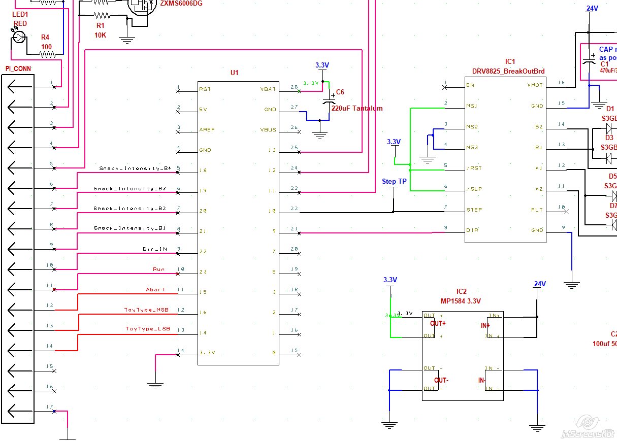
Attached is the schematic of the circuit. I have not installed IC1 (stepper logic chip). All working voltages (3.3V power rail) are correct and no shorts.
I am using the DRV8825 driver (Pololu item #: 2133).
So what might be wrong?
Thank you for sharing your wisdom. 
Hello.
Could you try removing the DRV8825 from your setup and setting VREF with only the following connections to see if anything changes?
- motor power (VMOT and GND)
- nRESET and nSLEEP pin to logic high (2.5 - 5.25 V)
- common GND with the logic source
Also, could you post some pictures of your actual setup showing all of your connections, as well as some close-up pictures of both sides of your DRV8825 carrier? Please include a picture showing how you are measuring VREF.
Brandon
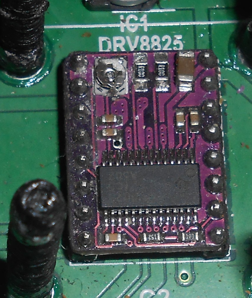
I can not remove the DRV8825 carrier, because it is soldered to the PCB. Since it soldered to the PCB I can not supply a picture of the bottom of the DRV8825 carrier.
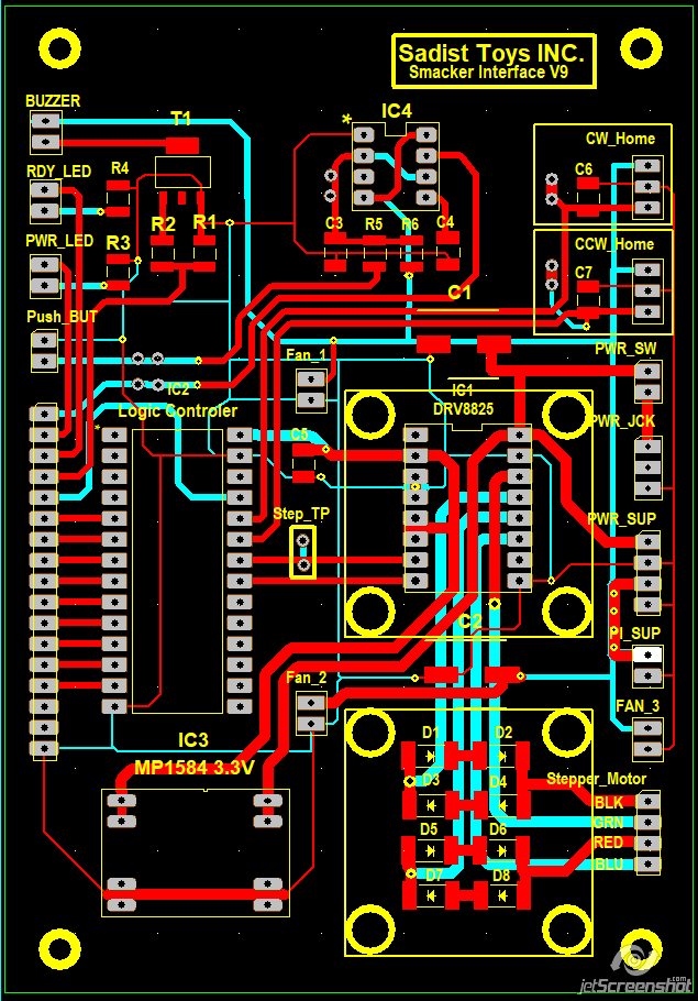
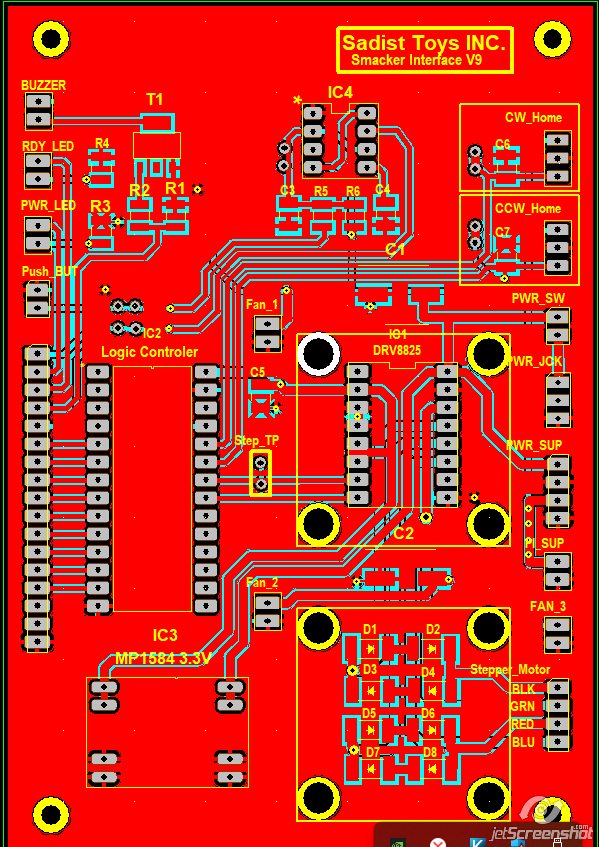
I have attached a screenshot of the PCB (ground planes turn off to reveal the trace routing).
With the logic controller (IC2) not installed only the connections are what you suggested.
>> VMOT = 24VDC
>> GND = GND
>> nRESET & NSLEEP = 3.3VDC
>> Mode = 2 (half stepping)
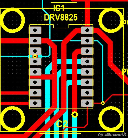
Are the ground connections on your board really just thin traces as shown in your picture or are you hiding the ground planes to make it easier to follow?
Could you post some pictures of your actual setup, including ones that show how you measured VREF and some close-ups of the DRV8825 carrier board so I can inspect the components and see your soldering (even if you can’t remove it)? Also, did you test the DRV8825 carrier separately before soldering it into your system?
Brandon
Yes, the GRND traces are very thin and can not handle the required current. I had to add these to make my PCB CAD software (DesignSpark) happy. Then when I do the GND planes (top and bottom layers) those trace mergers becoming the copper pour.
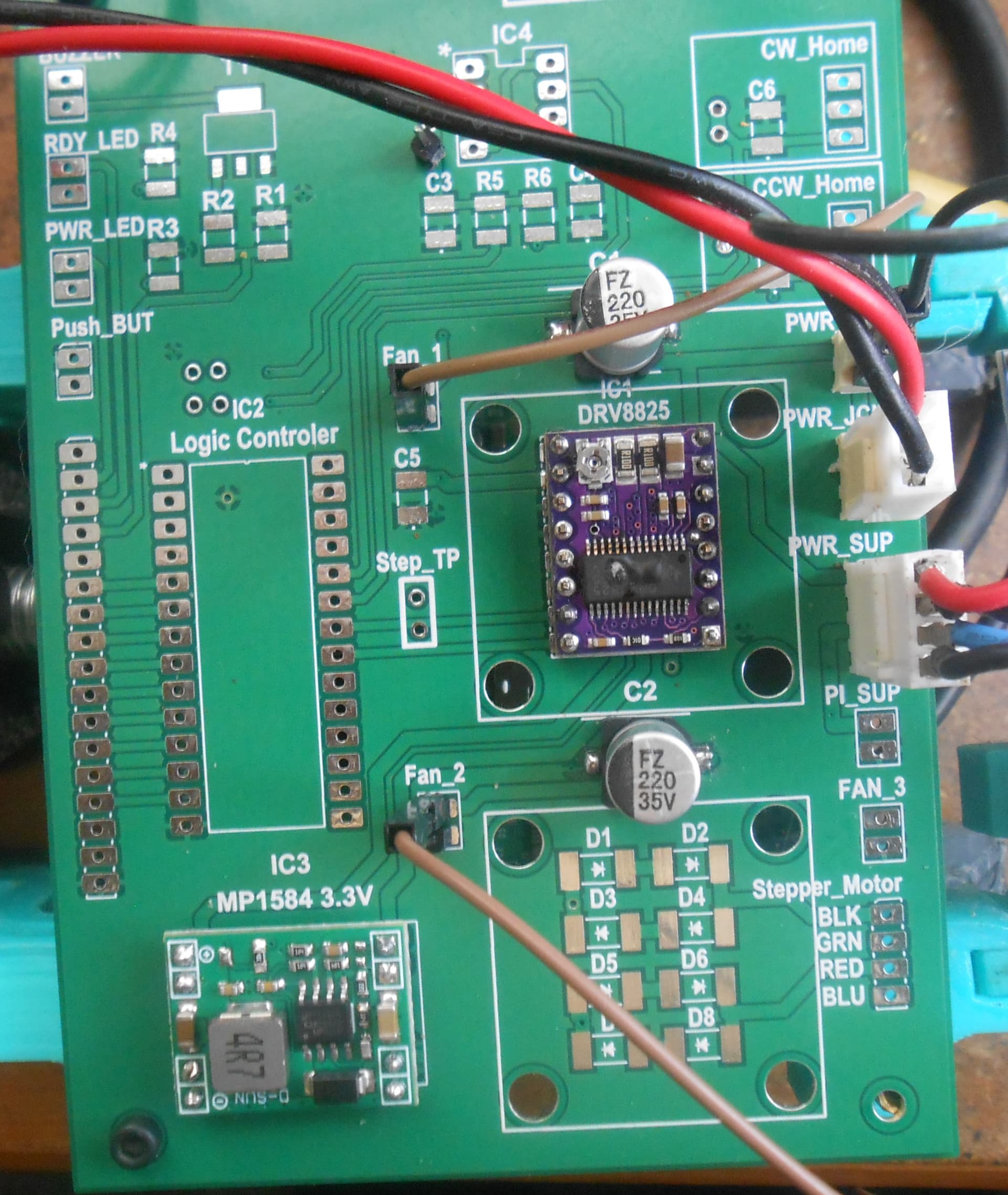
Here are the pictures that you asked for.
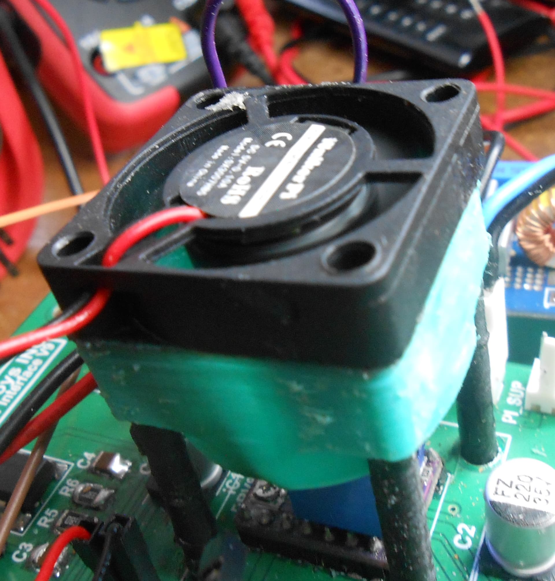
The 4 posts are 3D-printed fan supports. I agree that the driver chip really does not or required but I just want to keep the chip cool and happy
It’s hard to tell from the pictures, but your soldering looks like it’s probably okay. Unfortunately, that is not a genuine Pololu board, so we cannot offer additional support for it. Also, please note that our documentation (such as the VREF formula) probably isn’t valid for knockoff boards like that either. You might try contacting the manufacturer or retailer you got it from to see if they have any suggestions.
For future reference, if you want to be sure that you are ordering genuine Pololu products, then you can order through our website, or you can get them from our authorized distributors.
Brandon
I do not know to prove it is not a knot-off, but one I bought from you guys.
Thank you for sharing your wisdom with me. I will try again with a spare PCB board.
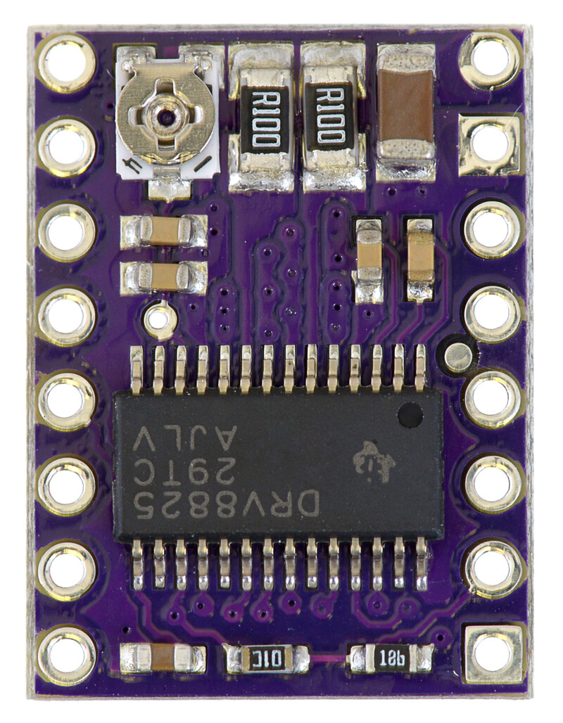
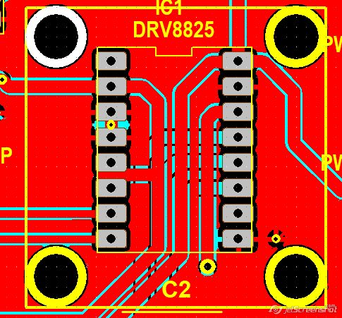
There are enough physical differences in the unit shown in your pictures for us to be certain that specific board is not a product we manufactured. For example, we have never made these modules with rounded corners, and our units all have square ground pads. Also, the traces are notably different:
Perhaps you are confusing it with other similar-looking units you did buy from us directly?
Brandon
WOW, I do not know what to say but there is a huge difference between your board and mine. I have ordered a new one (Web order #1027625). I will let you know when I receive it and tested.
Have a great day.
FYI::
I received the new drive. While I was trying to set Vref (675mV) a red spot and smoke appeared on the main chip appeared, telling me I somehow blew the chip.
That pot is extremely sensitive making it hard to set Vref.
P.S:
I have ordered a new.
I’m sorry to hear you had problems with your latest driver. That failure does not sound normal; in general, damage like that should not happen from just turning the potentiometer. Is it possible that you might have accidentally shorted something (e.g. with your screwdriver or your multimeter probe)?
With your new replacement unit, I recommend setting the current limit before connecting the driver to the rest of your setup by just supplying logic power (2.5-5.25V) to nRESET and nSLEEP as well as motor power (8.2-45V) to VMOT (without anything else connected, including a stepper motor).
In case it helps, a small flat head screwdriver typically works better than a Phillips for adjusting the potentiometer, even though the potentiometer looks like it is intended for a Phillips head.
Brandon
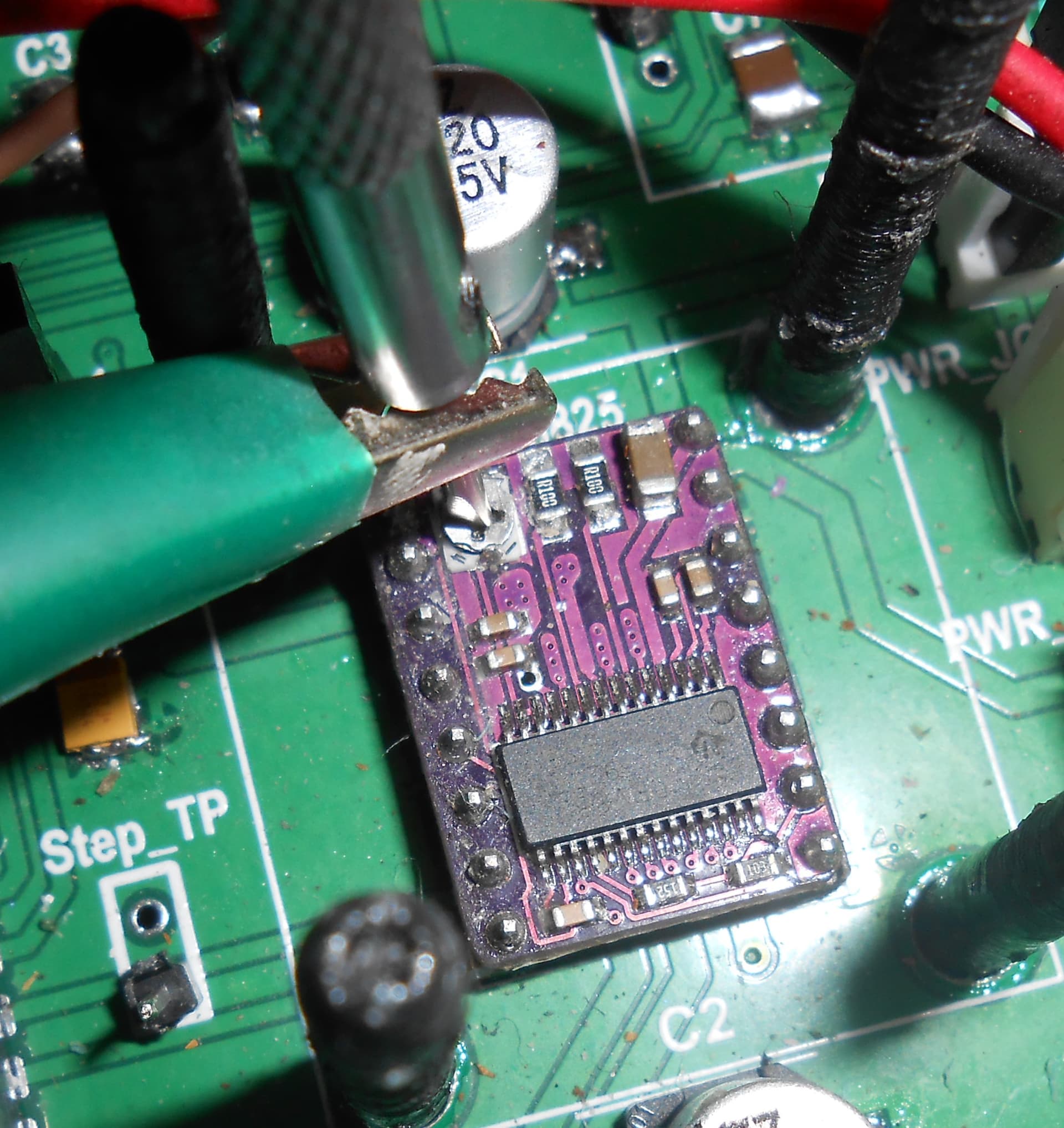
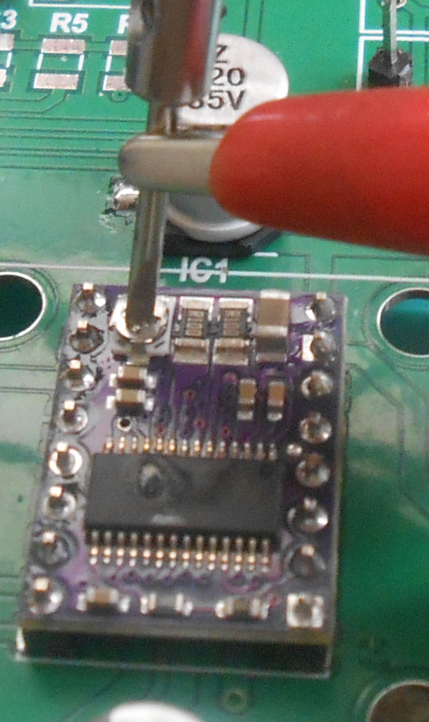
It could be possible I somehow shorted the pot. Here is a picture of how I tried to set Vref. As you can see I used a jewel flat screw driver to adjust the Vref.
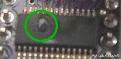
Here is a picture of the chip melted spot ( green circle ).
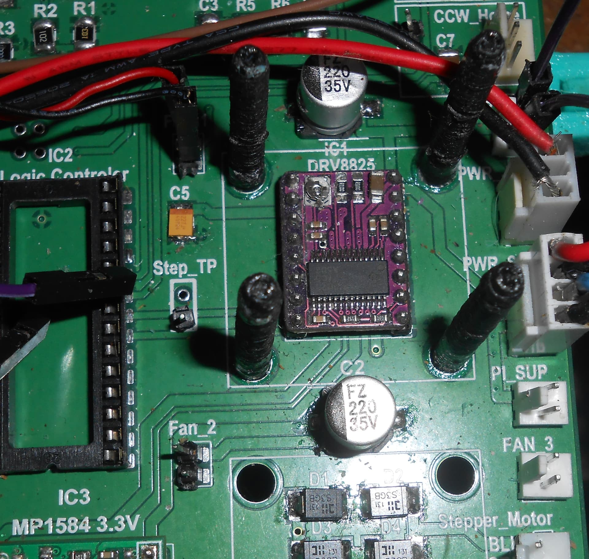
Yes, I used the minimum circuits as shown in this picture. I installed the bare minimum parts (3.3 Vdc regulator, 2X 220uf caps, and the driver). I am powering the board with a 24V power supply. Yes, I checked all voltages before I installed the driver.
Nothing in your pictures stands out to me as problematic, so hopefully the replacement driver works without similar issues; have you ever used this motherboard with a DRV8825 driver successfully?
By the way, it looks like some of the pins on your DRV8825 board could use some more solder, although I do not suspect that caused the problem.
Brandon
Yes, in the previous version of the motherboard, the driver worked properly. However, there was a problem with the overall design. The main problem is that Python code being an Interpreted Programming language it is unable to provide the micro-second timing needed for the required stepper motor operations. There is another unrelated issue with the previous motherboard. The design has a push button that interrupts the Python code. Even using the debounce function with a 15 mill-second debounce time. I got false triggers. So this new motherboard includes a debounce circuit using an LM555 chip.
With the major problem(s) with stepper motor timing, I had no choice but to redesign the motherboard with a logic controller (Arduino Itsy Bitsy 32u4 3V). Which can provide the required microsecond timing. Starting with the previous motherboard PCB design I left the right side alone and widened the board to the left. Meaning I left the working driver PCB traces alone,
Yes, I also noticed some of the pins do not have the required solder.
Just a friendly suggestion enlarging the Vref test via a little so a wire can be soldered to this test point. To help seting the required Vref voltage.
Richard
Success
I have been able to set the VREF to 675mV and the driver is working driving the stepper motor.
Just a curiosity questing if I may. Is the wiring color code (BLK/GREEN coil A and RED/BLUE coil B) industry standard?
Again thank you for sharing your wisdom. 
I am glad to hear you got one working! Thank you for letting us know.
In general, wire coloring can vary depending on the stepper motor manufacturers, but from my experience the BLK/GREEN and RED/BLUE pairing is a convention a lot of them follow. If you’re in doubt, you could measure the resistance between each wire to find the pairs that belong to each coil.
Brandon
I am sorry to bother you again with a question. The motor is extremely noisy and it is very hot to the touch. So what could be the problem?
I am using 24VDC to drive the motor with the Vref set at 670mv. With the mode set to 2 (making each step .9 degrees per step)
Should I take the mode up to 8 making 0.225 degrees per step)?
It is normal for stepper motors and stepper motor drivers to get very hot when operating. As long as the current limit is set equal to less than or equal to the motor’s rated current per phase, it should be fine. You could try reducing the current to run cooler, but please note that this can impact the speed and torque that the motor can achieve.
As far as the noise, if it is coming from vibrations from the motor stepping, then increasing the microstepping resolution could help. You could also try using some kind of vibration dampening mounting solution (which I do not have any specific recommendations for). If you’re referring to the audible hum or high pitched whine, this is relatively common with using stepper motors, and there is not a single method guaranteed to eliminate it, but there are some different ways you could try to reduce it. For example, here’s a web page that describes the source of stepper motor noise and gives some general suggestions for how you could try to deal with it.
Brandon
Thanks for the link. I learn a lot from it.
Increasing the mode from half step to 1/8 step has been suggested. I am relaying the PCB for this new mode value (M0 = 1, M1 = 1, and M2 = 0).
It also has been suggested I try a different motor. I have been looking at your motor (item #: 2267) Which one do you suggest I try? The max step rate is 10000 steps per second with Mot at 24Vdc. What does Each phase draws 1.7 A at 2.8 V, mean? It states each coil current is 1.7 A, which makes Vref 850 mV. Am I correct?
Richard
I do not know your system’s requirements, so I cannot make any specific suggestions for a stepper motor. However, I generally recommend checking the pullout torque curve in the stepper motor datasheet (found under the Resources tab) to get a sense of what the motor is capable of.
In this case, “Each phase draws 1.7 A at 2.8 V” is essentially the same as saying that the motor has a rated voltage of 2.8V and a current per phase of 1.7A. Please note that the DRV8825 carrier can only do around 1.5A per phase without additional cooling, so if you use the #2267 motor, you should set the current limit to 1.5A (VREF=0.75V) since it is the lesser of the two (which will also slightly reduce the speed and torque the motor is capable of).
Brandon