Hello everyone, I am working on a more accurate Robot Arm.
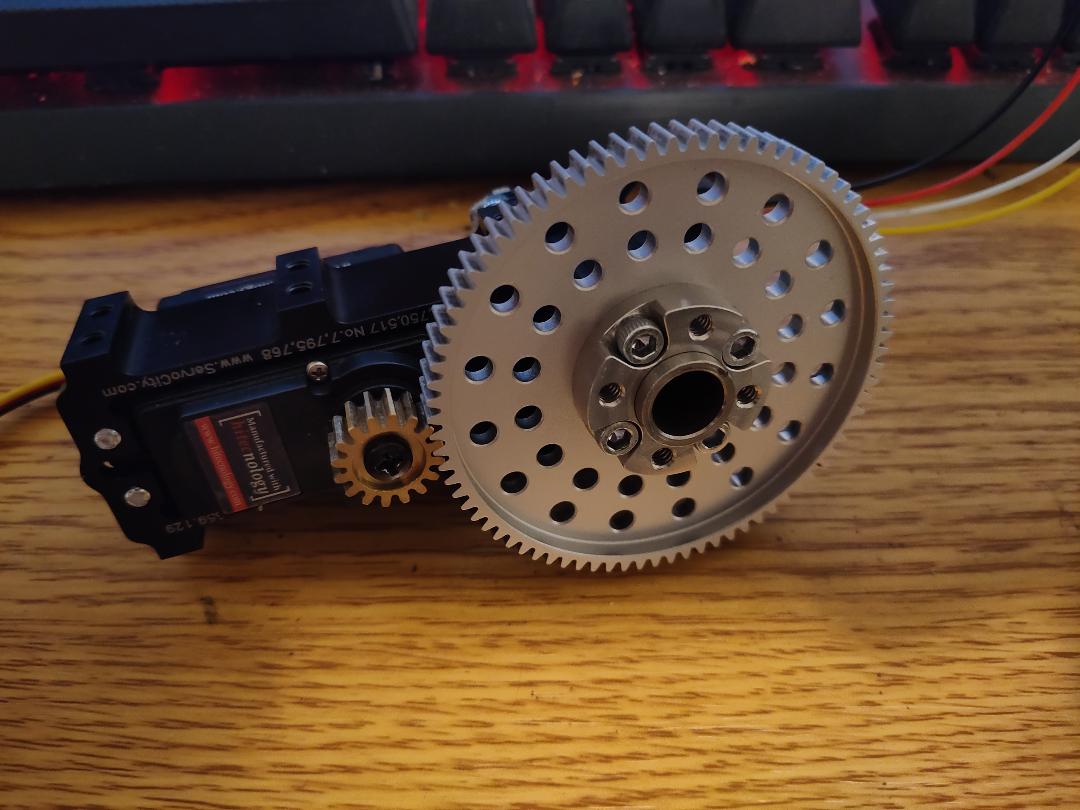
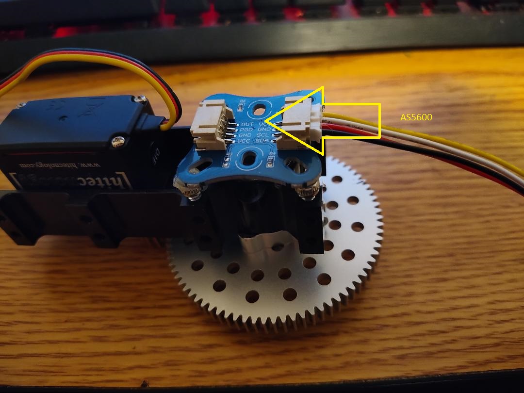
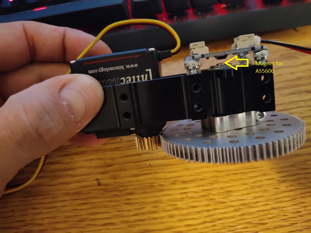
To make it more accurate and less “squirrely”, I am overriding the Servos’ built in potentiometer and instead am using an AS5600 on the output shaft at the main gear Using Servo-City 84:12 Gears.
I also have the servos set to continuous mode.
Everything works great, but using an ESP32 to ramp up and slow down several servos (similar to how the Maestro does it) really takes a toll on the ESP32, doesn’t seem like much room to use it with other sensors I plan to use at the same time.
The AS5600 has a 12 bit output (0-4095), and uses either I2C or PWM - I am currently using I2C, but it looks like I would have to use the PWM out to the Maestro.
Can the AS5600 can be connected to the Maestro as a PWM input? I currently have 4 servos, so I will need at least 4x AS5600 inputs and an additional 4x Servo PWM outputs.
Link to my AS5600:
https://www.aliexpress.us/item/3256804780240210.html?spm=a2g0o.productlist.main.15.239e6ca4QYgiks&algo_pvid=a8e967b8-ef56-4e48-ae33-d2f98c6b62d5&algo_exp_id=a8e967b8-ef56-4e48-ae33-d2f98c6b62d5-7&pdp_npi=3%40dis!USD!2.21!1.72!!!2.21!!%40211bd7d616901074721893540d0778!12000031183743893!sea!US!0&curPageLogUid=lmaYOztw79kz
I am not familiar with that sensor, but from the information in your link the “PWM” output is described as a “PWM/analog signal output”. So, I suspect is a duty-cycle based PWM signal.
Maestro channels 0-11 are capable of reading analog inputs. If that signal is a duty cycle based PWM, then it is not a pure analog signal, but you might be able to read it with the Maestro by adding a filter to it. Additionally, the analog input on the Maestro is 10-bit (0-1023), so you would be losing some resolution.
The 32-bit microprocessor on the ESP32 should generally be capable of more than the 8-bit one of the Maestro. You might consider using the ESP32 to read your feedback sensors and then having it drive the servos through the Maestro using a TTL serial interface. This could help remove some overhead from the ESP32 so it doesn’t have to generate the servo signals and manage ramping them up and down.
Brandon
1 Like
Thank you, I was kinda afraid of that, so what you mentioned was going to be my next option. It sounds like a perfect idea, but I cant wrap my head around the timing of it.
Since the servos are set to continuous, and if I had the Maesteo accel set to 1, how soon before reaching the destination should I tell the maestro to stop, so the servos wind down and stop at the correct destination?
Is there a formula that the maestro uses? What if later I decide I prefer to use Maestro accel at 5 instead of 1? Or speed up ( or slow down) the servo max speed?
Lets say I want to stop when the servos’ AS5600 reads 2048 (halfway). If I am currently at 1000, and I tell it to stop at 2048, that wont work because that is actually the point that the servo begins to wind down. So it will actually roll past 2048. If I try to roll it back, it’ll ramp up and then down and probably still not stop at 2048.
Unless you can think of something else, that is my dilemma at the moment. Any help here would be greatly appreciated. The only option I can think of is setting the accel to 0 right at the very end (like, say, at 2047 change accel to 0, then reset back to 1 for the next move), but I would still like to get the formula right if at all possible.
Just to clarify, are you using continuous rotation servos (i.e. open-loop speed control) with an external sensor on the output shaft to do closed-loop position control? If that’s the case, you will probably want to use something like a PID controller to correct for errors.
The speed setting on the Maestro controls how quickly the pulse width signal can change and the acceleration controls how quickly the speed can change. So, when you’re using continuous rotation servos the “speed” setting is actually controlling the acceleration of the servo (since the pulse width itself is controlling the speed and not the position). Similarly, “acceleration” is actually controlling the jerk.
You can find more information about the units for the speed and acceleration settings in the “Channel Settings” section of the Maestro user’s guide.
By the way, please note that the acceleration limit does not ramp the speed down to stop like you described (i.e. it does not decelerate).
Brandon
1 Like
Brandon,
I really don’t know the difference between open and closed loop, but I can tell you that its a Hitec HSR-M9382TH servo that has an “app”, if you will, that can set it to either normal control or continuous along with a ton of other settings. FYI, All of the “innards” of the servo are in tact and have not been tampered with. I am using the AS5600 for position read to the ESP32.
Maybe these Pictures can help:
I do understand that 1500 = Stop, and around 1537 it just starts to move forward at the slowest possible speed and anything above that is increased speed. (Same for below 1500: 1483 is slowest reverse speed, and lower than that increases the speed in reverse). That is currently how I am controlling the ramp up to speed, and ramp down to stop with the ESP32.
My hope was that the Accelerate on the Maestro would handle all of the hard calculating of ramp up and ramp down to the desired speed for forward and reverse to take the strain off the ESP32.
I was hoping to have the ESP32 tell the Maestro to go, say 1750 Servo Speed to Destination of, say position 3000 (remember the AS5600 reads positions between 0-4095), the Maestro would ramp up to 1750 Servo Speed, then (and I need this formula) when its at “x” less than the destination, have the ESP32 tell the Maestro to stop - and the Maestro should wind down the servo close to or at the destination position. I’m not sure if this makes sense.
“By the way, please note that the acceleration limit does not ramp the speed down to stop like you described (i.e. it does not decelerate)”
I’m assuming you mean in continuous mode, or am I misunderstanding you? I could have sworn when I first had the Maestro and continuous servo connected back when I started this project that it was decelerating and accelerating while using the slider in the Maestro app, just like my other servos do. I will have to set it back up and confirm that I am indeed crazy (as if I need more confirmation lol), this may all be a moot point if that is the case
Edit: I just checked, it does indeed ramp down (and up) in continuous mode like the other servos. Glad I’m not crazy at least in that regard, lol.
I do not think it would be practical to control the servo the way you are describing (i.e. try to time when to tell the servo to stop). I suspect that will result in less accuracy than just using the servo’s built-in position control. Using a PID control algorithm to constantly update the speed of the servo based on the error would be much more accurate. The Maestro’s speed and acceleration settings could be used to help control (limit) the speed and smooth out the motion in that case, but wouldn’t be part of your program’s calculations.
Sorry about the confusion, you are correct, the Maestro will slow the speed down as it approaches the set target position. You can find a “Maestro Movement Calculator” linked in the “Resources” tab of the Maestro product page that can give you an estimation for how long the Maestro will take to perform a servo movement based on the speed and acceleration settings. However, I do not think the formula that the Maestro uses will help with your continuous rotation servos since they are essentially acting as brushed DC motors; the speed will vary depending on the load, which will vary depending on the mechanics of the system (i.e. the angles of the joints in your robotic arm). Since you are using your own feedback, I would highly recommend doing your own control algorithm instead of relying on the timing. You might even consider reducing the servo period on the Maestro (which you can do under the “Channel Settings” tab of the Maestro Control Center) so the updates from the PID algorithm can reach the servo faster.
Brandon
1 Like
Brandon,
Thanks again.
Wow, There’s a lot to take in for a PID algorithm. Do they have explanation for dummies somewhere lol? Actually I’m a doer, and not so much a reader. Arduino examples would help me tremendously. But I can’t find one that is servo position based.
What I’m doing right now with the esp32 seems pretty accurate to me and I’m just gonna roll with it for now. Occasional very slight overshoot but it corrects itself immediately. I will keep reading about the PID because I am curious like that, just not sure how to implement it yet.
Btw, the entire reason I can’t use the internal pot is 1: it mildly shakes/fluctuates too much, but 2 when I first power it on the servos go haywire for a second or 2, so the arm always starts in a crazy position or worse, a position that will damage it. This is on non continuous (normal) servomode.
There are a lot of videos on YouTube explaining PID at various levels of complexity. For example, this video explains the PID coefficients in a basic way and is probably a good start for someone who isn’t already familiar with control systems.
If you have the time and want to dive deeper, this video by Dr. Christopher Lum from the University of Washington has a more thorough explanation:
The PID controller Wiki also has a lot of helpful information.
I do not have an example to point to that does specifically what you are looking for, but here is a quick pseudocode that might help get you started:
currentPosition = sensor reading;
proportional = targetPosition - currentPosition;
integral += proportional;
derivative = proportional - lastProportional;

correction = Kp * proportional + Ki * integral + Kd * derivative;
//Kp is the proportional coefficient, Ki is the integral coefficient, and Kd is the derivative coefficient. These values need to be tuned to your setup.

servoOutput = 6000 + correction;
//6000 is the target position to give the Maestro for a 1500μs pulse width, so when the correction is 0, the continuous rotation servo will stop.

lastProportional = proportional;
Tuning PID coefficients can take a lot of trial-and-error, especially if you haven’t done it before. You can find some various tuning methods on the PID controller Wiki, including information for Manual tuning. I’ve also had success in the past with the Ziegler–Nichols method (which starts similarly as manual tuning, but specifies a relationship between the coefficients from there).
Brandon
1 Like
Oh wow, I wasn’t expecting all of that. This forum rocks, and you do too Brandon. Looks like this project is gonna be a lot more than I thought when I started it. And I’m ok with that.
Thank you so much for getting me some great starting points, and the code too!
1 Like
Just a quick update: Been at this since my last post and I gotta say that even though I really like my old code and…well cuz I wrote it so I’m biased lol…this PID algorithm is working extremely well now! Thanks again for posting that pseudo code, that helped more than anything.
I added an interrupt to get the AS5600 position, made some adjustments to your code, and I also used Potentiometers and buttons to adjust Kp,Ki,Kd and it made things much simpler and quicker, this will be handy since some of my servos are externally geared with different ratios. I was gonna just use Serial, but I think this way will be more efficient in the real world testing once this arm is together.
This is moving snappy, and with the Maestro Acceleration and Deceleration its also smooth. I still have a bit more tuning as I just got this wrapped up and going this morning. I still haven’t ran with more than one servo at once, so I can’t say how efficient everything will be running 7 servos simultaneously.
The next challenge I see coming up is that there will be a lot of wires in a little space running throughout the length of this arm, and right now I’m using I2C to get my positions from AS5600. Is using I2C a bad idea? I have tested and it works fine from 3 feet of wire on its own so distance shouldn’t be an issue since my furthest AS5600 Servo would be less than 2 feet out, but this may be problematic with 7 servos, 4 of which will be using the AS5600 on I2C. The other 3 servos at wrist and gripper would be standard servo controlled from the maestro (i.e. not continuous), I need to run standard servo wires for them.
As for these AS5600 servos I could try using PWM signals instead of I2C to the ESP32, which would be 1 less wire per servo (and perhaps a better signal than I2C intertwined with the other wires running throughout). Would this this be more beneficial and worth the extra effort? Or I am open to other ideas/methods of running wires (and keeping them out of the gears - which I will state from experience is a very, VERY bad idea…).
I’m glad the PID control is working well for you. In general, I2C is intended for short distances, but it sounds like you’ve already tested your setup and it was fine, so that covers the main concern I would have. In case you weren’t already doing this, please note that when using multiple devices it is common for each one have a unique address so you can individually address them all while connecting them to the same bus. So, that might help reduce the amount of wiring required.
Brandon