Bipolar Stepper Motor via 36v4 Driver and Arduino Leonardo

I really appreciate all the information provided in the Pololu Forum and the product pages. Perhaps I’m too much of a newbie, but despite harvesting all the information I can, I’m struggling to get my stepper motor up and running. Try as I may, I’m getting no motion, voltage, or current at the pinouts to the stepper motor.

There may be a few questionable aspects of my setup, but hopefully they don’t expose me here as too much of an amateur. (1) I’m using a reclaimed ATX power supply to provide 12 V for my external power supply (measured at 11.68 V using DVM). I’m not able to confirm the current, but the label on the ATX claims 17A at 12V. (2) My stepper motor is a a NEMA17 (Pololu item #2267). According to the datasheet, the rated current is 1.68A, so I have set setCurrentMilliamps36v4() to 1680mA in the code. Hopefully this is not confusing the rated current with the max allowable current. Also, from the datasheet, I’m supposing the black wire is AOut1 and the red wire is BOut1 and I am not reversing the coils. (3) As the title to the post suggests, I am attempting to use the 36v4 high-power stepper motor driver. I assume it is compatible with this NEMA17 motor and my power supply. (4) I’ve read several mentions of the common ground between logic and external power supply and hopefully I have made the appropriate connections. (5) I assuming my brown wire connection from Arduino ground to logic power supply is redundant or completely wrong, but feel free to educate me. (6) It’s possible I am doing something wrong in the Arduino GUI v1.8.13, such as not using the SPI or HighPowerStepperDriver libraries properly, but my code always compiles and examples from these libraries do open for me in the GUI.

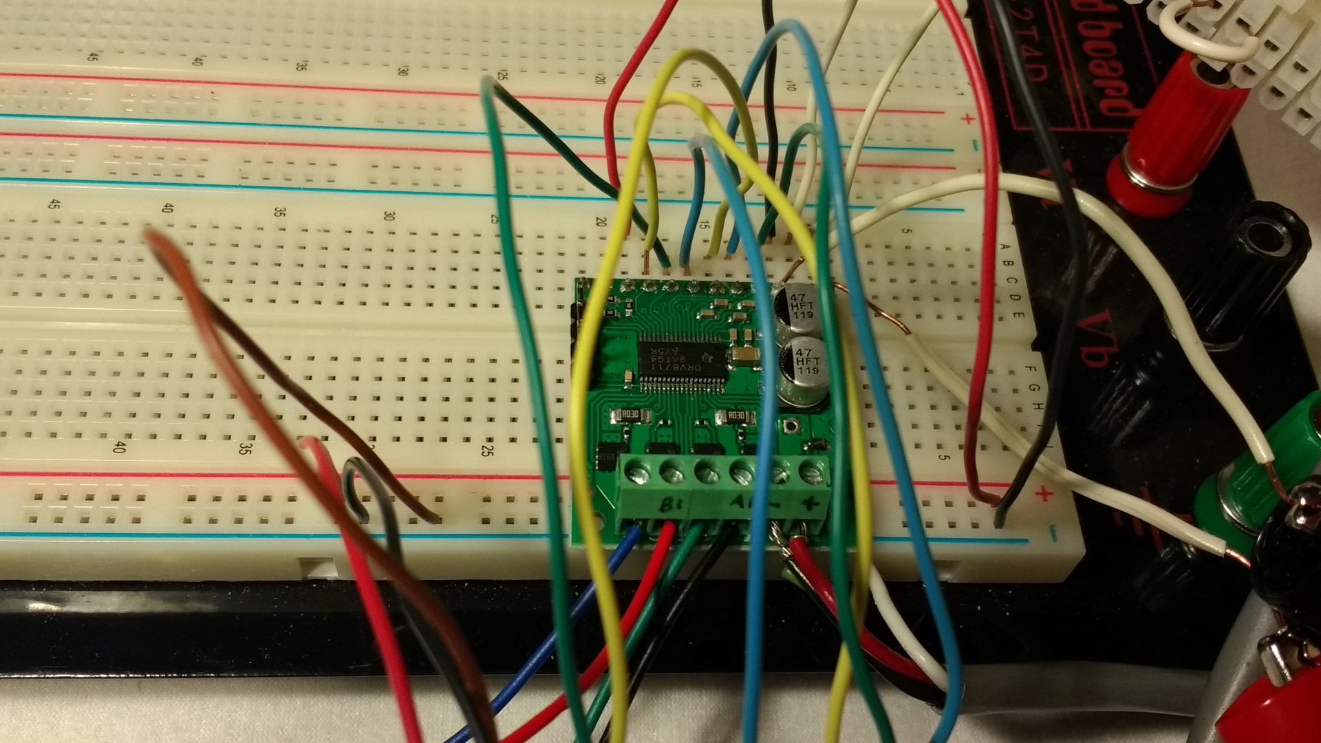
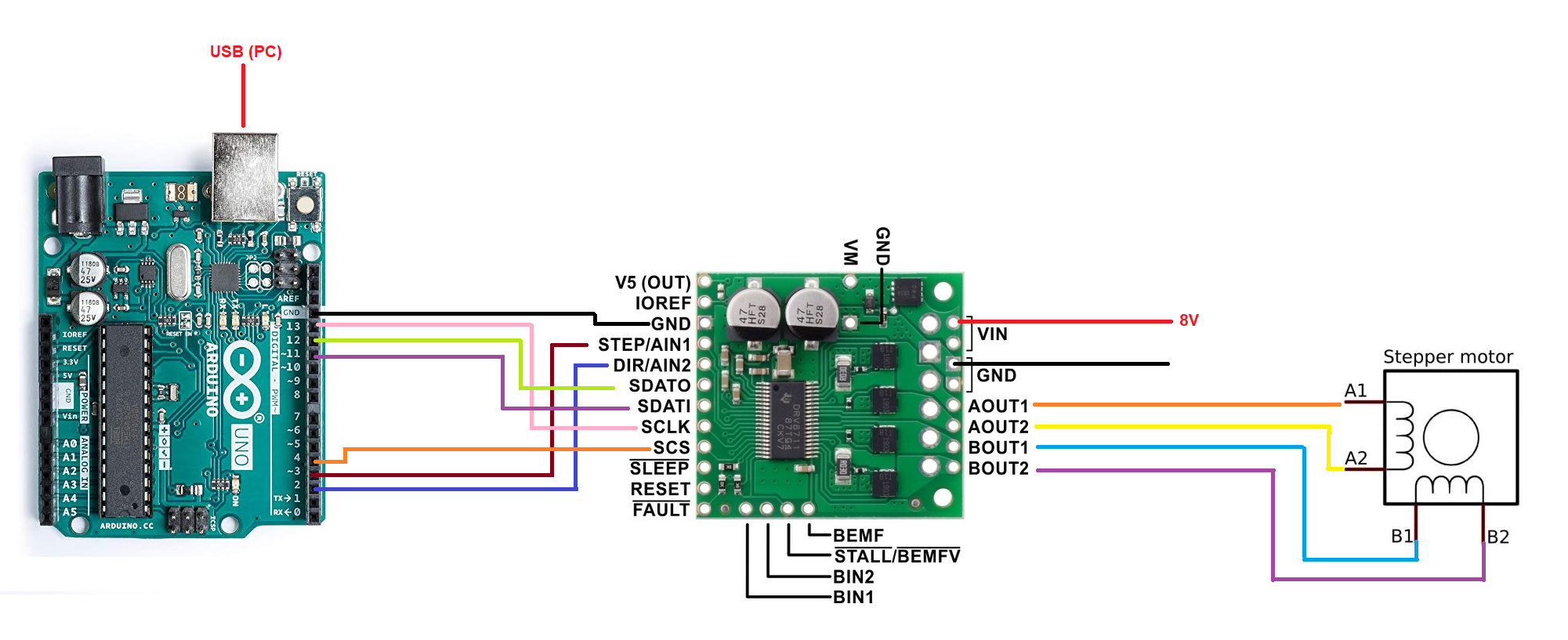
I’ve include pictures of my connections, but here is a rundown as well (including DVM voltages at the relevant pinouts):

Arduino Driver Voltage


(jumper to IOREF) V5 (out) 4.98
(jumper to V5) IORef 4.98
Power GND GND n/a
D3 STEP 0
D2 DIR 0
D12 (MISO) SDATO 4.97
D11 (MOSI) SDATI 0
D13 (SCK) SCLK 0
D4 SCS 0.08
Power 5V Out SLP 5.03
n/a RST 0
n/a FLT 4.97

Of course, I’m working with the BasicSteppingSPI.ino

example and trying to get it to work. Any insight would be greatly appreciated. Here is my code for good measure:

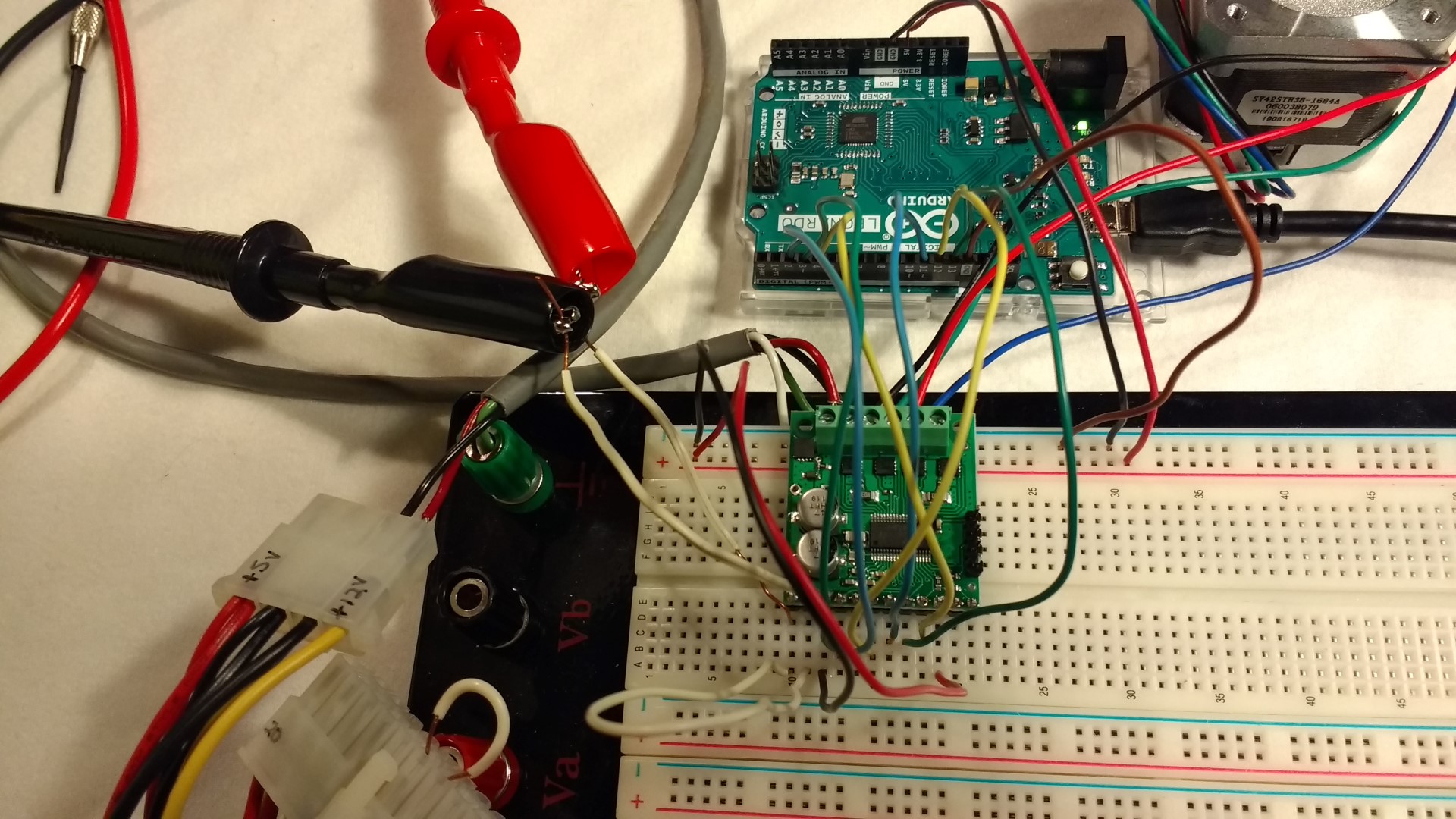
// This example shows basic use of a Pololu High Power Stepper Motor Driver.

#include <SPI.h>
#include <HighPowerStepperDriver.h>

const uint8_t CSPin = 4;

// This period is the length of the delay between steps, which controls the
// stepper motor's speed.  You can increase the delay to make the stepper motor
// go slower.  If you decrease the delay, the stepper motor will go faster, but
// there is a limit to how fast it can go before it starts missing steps.
const uint16_t StepPeriodUs = 2000;

HighPowerStepperDriver sd;

void setup()
{
  // Setup serial communication
  Serial.begin(9600);
  while(!Serial);
  Serial.println("--- My sketch has started ---");
  delay(3000);
	
  SPI.begin();
  sd.setChipSelectPin(CSPin);
  
  // Give the driver some time to power up.
  delay(1);

  // Reset the driver to its default settings and clear latched status
  // conditions.
  sd.resetSettings();
  sd.clearStatus();

  // Select auto mixed decay.  TI's DRV8711 documentation recommends this mode
  // for most applications, and we find that it usually works well.
  sd.setDecayMode(HPSDDecayMode::AutoMixed);

  // Set the current limit. You should change the number here to an appropriate
  // value for your particular system.
  sd.setCurrentMilliamps36v4(1680);

  // Set the number of microsteps that correspond to one full step.
  sd.setStepMode(HPSDStepMode::MicroStep32);

  // Enable the motor outputs.
  sd.enableDriver();
}

void loop()
{
  // Step in the default direction 1000 times.
  sd.setDirection(0);
  for(unsigned int x = 0; x < 1000; x++)
  {
    sd.step();
    delayMicroseconds(StepPeriodUs);
  }
  
  // Wait for 300 ms.
  while(!Serial);
  Serial.println("Completed stepping in one direction");
  delay(300);

  // Step in the other direction 1000 times.
  sd.setDirection(1);
  for(unsigned int x = 0; x < 1000; x++)
  {
    sd.step();
    delayMicroseconds(StepPeriodUs);
  }

  // Wait for 300 ms.
  while(!Serial);
  Serial.println("Completed stepping in other direction");
  delay(300);

Thank you for posting so much detail about your setup and what you’ve tried. There is a lot going on in your pictures, but one thing I noticed right away is that it looks like you aren’t connecting to the SPI pins. The SCLK, SDATI, and SDATO pins on the 36v4 driver should be connected to the SCK, MOSI, and MISO pins on your Arduino respectively (it looks like you have them connected to pins 13, 11, and 12). For reference, here is a pinout diagram for the Arduino Leonardo; the SCK, MOSI, and MISO pins are located on the 2x3 ICSP header:

Also, I noticed your motor power wires going into the terminal blocks on the 36v4 board look very close to shorting together (especially with stranded wire, since even a single stray strand can cause major problems). I recommend twisting them tighter and either inserting them farther into the terminal block, or trimming them down if necessary so there isn’t as much bare wire exposed.

Before doing too much more troubleshooting, could you try fixing your SPI connections and seeing if you get any signs of life when running the unmodified BasicSteppingSPI.ino example?

Brandon

Thank you so much for responding, and responding so quickly! I was wondering about the 2x3 ICSP header. I certainly noted those connections in other examples (e.g. Two 36v4 drivers and two stepper motors - #11 by BenJSharman). As those are dedicated pins, that would be the obvious route to go. Unfortunately, left to my own devices, I reached for digital pins 11-13 as a substitute for two reasons: First, I don’t have any of those fancy, jumper wires with male and female ends, rather just salvaged 20 AWG copper wire. Perhaps I skipped the simple route due to lack of supplies and no way to easily connect to the ICSP header (I will work on getting some jumpers, so bear with me). Second, with the simple route blocked, I held out hope that the Leonardo digital pins 11-13 would work as an alternative based on my reading of the Arduino.cc pinout diagram (see picture). But now I’m gathering that those pins may only be used that way in some secondary configurations. Of course, I noticed that I made no explicit calls to pins 11-13, but that didn’t prevent my wishful thinking.

Thanks also for your sharp eye which noticed the somewhat frayed ends of my power supply feed wires. I appreciate the nugget of common-sense advice. I will clean up those wires.

I have some good news to report: the stepper motor is working. While they aren’t very firm connections, I temporarily looped the three wires for the ICSP around their relevant male pins and carefully plugged in the Arduino. Rather than three connections at D11-D13, I now have:

Arduino Driver


ICSP-1 SDATO
ICSP-4 SDATI
ICSP-3 SCLK

I’ve been very careful not to cross wires or lose connections during this brief test and will proceed further once I have better jumpers. Thank you very much for your help and input.

However, I still have seen references in this forum to the use of digital pins 11-13 for SPI connections on the Arduino Uno (https://forum.pololu.com/uploads/default/original/2X/b/b547317be8011ed8ce967481e58323726e377794.jpeg and https://forum.pololu.com/uploads/default/original/2X/c/c7fc53030f661d0dd41c80d9fb6f3a3b12200fd6.jpeg) with no comments about re-routing these wires to the ICSP header. Similarly, while I’m not familiar with your Arduino boards, in Pololu’s example wiring with an A-Star 32U4 Mini SV (Pololu High-Power Stepper Motor Driver 36v4) the ICSP headers are also avoided. Can someone explain the scenarios where the digital pins can be used in place of the ICSP?

I am glad you got it working! If you plan on doing more prototyping with electronics, I recommend getting an assortment of Premium Jumper Wires so you do not have to rely on questionable connections.

The schematics for the Arduino Leonardo show that MISO, MOSI, and SCK are not connected to 11, 12, and 13, so I suspect their pinout diagram has an error in it. The Arduino Uno R3 is a different board and can use pins 11-13 for SPI communication.

While our A-Star 32U4 boards do use the same ATmega32U4 AVR as the Arduino Leonardo, the pinout of our A-Star 32U4 Mini boards is different; they provide access to the SPI pins on the breadboard-compatible pins on the sides of the board.

Brandon