
I can’t seem to get my USB Programmer to recognize my Baby-O. It’s red LED is blinking, according to the manual the baby-o is under powered. I have it connected to 4 AA’s .
Any ideas
I can’t seem to get my USB Programmer to recognize my Baby-O. It’s red LED is blinking, according to the manual the baby-o is under powered. I have it connected to 4 AA’s .
Any ideas
Hello.
Your batteries new/freshly charged? Can you describe how you have everything connected? It would also be very helpful if you could post a picture of your setup.
- Ben
The batteries are fresh, I’m on windows machine. I think I know the reason but i’m not sure. I put the header pins on backwards. The ISP header is on the bottom of the board(baby-O) and the others are on top. But I thought I still had pin 1 correct.
I don’t have a camera available right now. 
I think I’m gonna have to make a custom cable to get pin 1 in the correct location.
Hello.
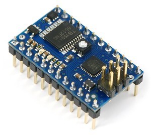
You are right, if you did not solder the 2x3 header like it is in this picture, it won’t work.
A custom cable should do the trick.
- Ryan
Ya I just figured that out. Mild case of ID1oT. 
Can you post a pic of the cable connected so I can figure this out.
I found a pic in the users guide, but it shows the red line on the left of the programmer. My cable is configured so that the red line is on the right. Because it’s polarized I can’t just switch ends.
So which side should the red line be on?
Hmmmm
Hello.
Sorry, I don’t have a picture like that handy right now, but you should be able to piece it together using the pin-1 indicator on the baby orangutan and this picture of how the female IDC connector works:
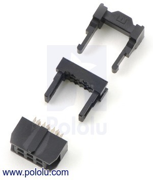
You can also use a multimeter’s continuity test to make sure you wired it correctly.
- Ryan
The red insulated wire goes to pin 1.
- Ryan
Ok this is crazy, according to the schematics my cable should work. Pin 1 is the bottom hole on the red line side. With the board flipped over like mine pin 1 is on the right hand side. So looking down at my board the pins look like this.
Pin 6 GND, Pin 4 MOSI/OC2, Pin 2 Vcc
Pin 5 RESET, Pin 3 SCK, Pin 1 MISO
Coming from the USB Programmer, Looking at the cable plugged into the board the pins look like this.
Pin 6 GND, Pin 4 MOSI/OC2, Pin 2 Vcc
Pin 5 RESET, Pin 3 SCK, Pin 1 MISO
Am I missing something?
If you have the ISP header soldered on the wrong side of the board, the only way you will be able to get something that works is to use a second cable or to flip one of your connectors by pulling it apart and clamping it back onto the ribbon cable after rotating it 180 degrees around the cable from its original orientation. There is no solution that involves just using the cable as you have it (short of desoldering the ISP header and putting it on the proper side of the board. Does this make sense?
- Ben
How do i remove the cable from the connector? I’ve been trying to figure it out.
I just looked at a cable when I got into work this morning, and I think it’s going to be very difficult for you to get the connector off without destroying it. I think your best bet is to buy a second cable and a double-sided male header strip. You can then use the header strip to connect the new cable to your old cable in a way that lets you make the proper connections between your Baby Orangutan and your programmer. If you go this route, I can explain in more detail what you need to do to make the right connections. Alternatively, you can cut the connector off of one end of your cable and replace it with a new IDC connector crimped on in the way I described in my previous post (I can post a picture for you if you choose this approach).
- Ben
To late I destroyed the connector trying to remove it. What if I just used 2 servo wires they fit on both the programmer and the Baby-O. I have 2 plugged into the programmer both white wires on the red stripe(pin1) side so if I do the opposite on the Baby-O then wouldn’t that work?
How about you just explain this? I think I can make it work.
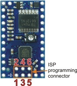
You should be able to make your own cable using two servo cables. Just make sure you connect them so that pin 1 on the programmer connects to pin 1 on the Baby Orangutan, pin 2 connects to pin 2, etc. The following pictures label the ISP pins on the programmer and Baby Orangutan:
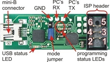
Note that the above picture shows an older version of our programmer, but the ISP pinout is the same as on our newer programmer.
Make sure you carefully plan what you’re doing and make the connections without power to the Baby Orangutan as plugging things in incorrectly is a good way to destroy electronics. Once you have your servo cables set up, I suggest you tap the connectors together and clearly mark which pin is pin 1 so that it will be easy to make the connection again later.
Do you still want me to explain the IDC-connector solution or are you good with using two servo cables?
- Ben
Thank you very much. I got i working, now I just need to program it! 
No thanks, this will work until the IDC connector I ordered gets here.
Thanks again
SubMicro
Great now I can’t get windows to recognize the programmer! 
I installed the drivers just as the manual said… arrgggg If it’s not one thing it’s another.
The green LED blinks slowly for a few seconds then stops and is no longer on or blinking
windoze says unrecognized usb device
The weird thing is before I had the cable problem it recognized it
Could you try disconnecting everything from the programmer, then plugging it in to USB and tell us if you get the same LED behavior? --David
yes I tried that still nothing. I mean same behavior