Arduino pro mini+DRV8835 Dual motor driver

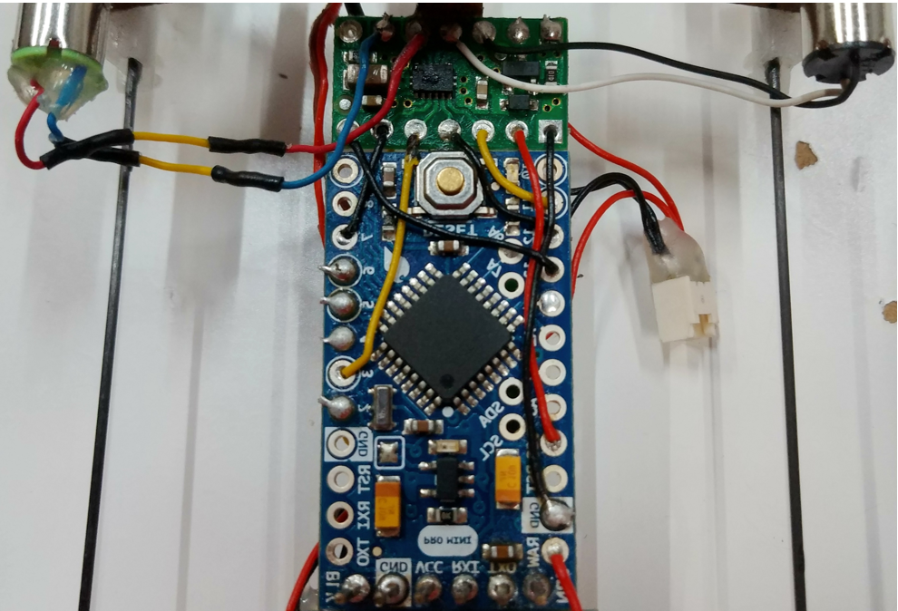
I want to drive two DC motors using DRV8835 with Adruino pro-mini.
Sometimes, two motors don’t work according to PWM signals.
I am using a PHASE/ENABLE mode.

My pin setting is as follows:
Driver <-------> Arduino pro-mini
BENBL pin <------> PWM pin 11
BPHASE pin <------> pin 12
AENBL pin <------> PWM pin 3
APHASE pin <------> pin 7

I am using 1s lipo battery and directly supply to VIN pin of the driver and Arduino raw pin together.
For powering to moter driver, I connect Vcc pin of Arduino with Vcc pin of driver.
Although HIGH signal should be transmitted to MODE pin in manual picture, I don’t transmit any signal to MODE pin.

When two motors work properly, the voltages in Bout1+Bout2 and Aout1+Aout2 are reasonable by PWM signals.
However, when two motors don’t work, although PWM signals are measured properly in Arudino pin,
the voltages in Bout1+Bout2 and Aout1+Aout2 are nearly zero and it starts beeping.

Am I missing something?
Thank you for your consideration.

Piecewise code:

int left_motor_in = 3;
int left_motor_out = 7;

int right_motor_in = 11;
int right_motor_out = 12;

%%%%%%%%%%%%%%%%%%%%%%%%%%%%%%%%

void setup() { 
init_motor();
}

%%%%%%%%%%%%%%%%%%%%%%%%%%%%%%%%

void loop(){
  left_motor_go(200);
  right_motor_go(200);
}

%%%%%%%%%%%%%%%%%%%%%%%%%%%%%%%%

void init_motor(){
  pinMode(left_motor_in, OUTPUT);
  pinMode(left_motor_out, OUTPUT);
  
  pinMode(right_motor_in, OUTPUT);
  pinMode(right_motor_out, OUTPUT);
}

//range:0<value<=255
void left_motor_go(int motor_speed){

  analogWrite(left_motor_in, motor_speed);
  digitalWrite(left_motor_out, LOW);
  
}

//range:0<value<=255
void right_motor_go(int motor_speed){

  analogWrite(right_motor_in, motor_speed);
  digitalWrite(right_motor_out, LOW);
  
}

Hello.

The MODE pin on the DRV8835 dual motor driver carrier board determines the control interface, so if the MODE pin is left disconnected (or low), the control interface is IN/IN, not PHASE/ENABLE. This is stated on the DRV8835’s product page. You need to set the MODE pin high if you want to operate the motor driver in PHASE/ENABLE mode.

By the way, you did not mention a ground connection between your Arduino and the DRV8835 carrier. Please note that the grounds of the two devices must be connected for them to function properly.

- Amanda

Thank you so much. I connected the MODE pin with some digitalWrite pin as your advice and
the picture shows our pin layout.

**Piecewise code:**
int MODE = 13;

int left_motor_in = 3;
int left_motor_out = 7;

int right_motor_in = 11;
int right_motor_out = 12;
%%%%%%%%%%%%%%%%%%%%%%%%%%%%%%%%
void setup() {
  Serial.begin(9600);
  Serial.println("Start");
  init_motor();
}
%%%%%%%%%%%%%%%%%%%%%%%%%%%%%%%%
void loop() {
  left_motor_go(200);
  right_motor_go(200);
}
%%%%%%%%%%%%%%%%%%%%%%%%%%%%%%%%
void init_motor(){
  pinMode(left_motor_in, OUTPUT);
  pinMode(left_motor_out, OUTPUT);
  
  pinMode(right_motor_in, OUTPUT);
  pinMode(right_motor_out, OUTPUT);

  pinMode(MODE, OUTPUT);
  digitalWrite(MODE, HIGH);
  }

//range:0<value<255
void left_motor_go(int motor_speed){
  analogWrite(left_motor_in, motor_speed);
  digitalWrite(left_motor_out, LOW);
 }
//range:0<value<255
void right_motor_go(int motor_speed){
  analogWrite(right_motor_in, motor_speed);
  digitalWrite(right_motor_out, LOW);
}

Although I connected the MODE pin to some digitalWrite pin, the same situation occurs.
the situation is that PWM signals are measured properly in Arudino pin,
the voltages in Bout1+Bout2 and Aout1+Aout2 are nearly zero and it starts beeping.

Sometimes, it starts beeping and I rotate the shaft of the motor a little bit,
then, the motors work and the beep sound disappears.
I am using full charged 1s 160 mAh lipo battery per trial.

Am I missing something?
Thank you for your consideration.

The wiring in your diagram and the code you posted look like they should work. Could you post some photos of your actual setup so that we can check the soldering and wiring? Also, what kind of motors are you using? Could you link to a datasheet or specifications for them?

Kevin

Thank you so much.
I don’t use a wiring connector to reduce weight, so I directly solder all wires to every pin.
Pins 5 and 6 are used for actuating two servo motors, respectively and
Pins 3 and 11 are used for drv8835 motor driver.
I supply power to the motor driver, Arduino, two DC motors, and two servo motors using one Lipo battery (140mAh).

The DC motor and servo I used are as follows:
Motor: Micron Wings
Servo motor: Micron Wings

The servos always operate well regardless of the operation of two DC motors.
In addition, PWM signals sent to the motor driver are generated properly from Arduino,
but the signals in A&Bout pins for DC motor are not generated sometimes.

Is it a problem to power all devices with a single battery?
Why beep sounds occur in the case of not moving DC motors?

Depending on how much current your LiPo battery can supply (this is sometimes given as a “C” rating), your battery might be fine for your system, but it would be a good idea to monitor its voltage while the servos and motors are running (or trying to run) to make sure it is not overloaded. If you have other batteries or power supplies you can test, that might also help you determine whether the battery is the problem.

The DRV8835 has built-in overcurrent protection that works by temporarily disabling the motor power (current chopping) when it detects that the current is too high. Sometimes, the protection is too sensitive and can activate when a motor draws too much current at startup, preventing the motor from starting to turn at all, and it can also cause a buzzing sound as the driver repeatedly but briefly tries to energize the motor and causes it to vibrate. However, we usually do not see this happen with low-power motors unless there are additional capacitors across the motor terminals (which are sometimes added to reduce electrical noise).

It doesn’t look like your motors are particularly high-power, and I don’t see any capacitors across them in your picture, so I’m not sure whether the overcurrent protection is causing the behavior you’re seeing. Is it easy for you to try some different motors with your setup?

Can you probe the motor outputs with an oscilloscope to see what they are doing when the motors fail to run?

Kevin