
I use the MC33926 or Jrk 21V 3 but I do not know how to connect.
I usel Arduino Due output 1 and 2, connect MC33926 M1IN2 and M1IN2 or M1D2 and M1D1. VDD uses 5 volts. VIN and GND use an external power supply. But no output.I do not know why this is so.
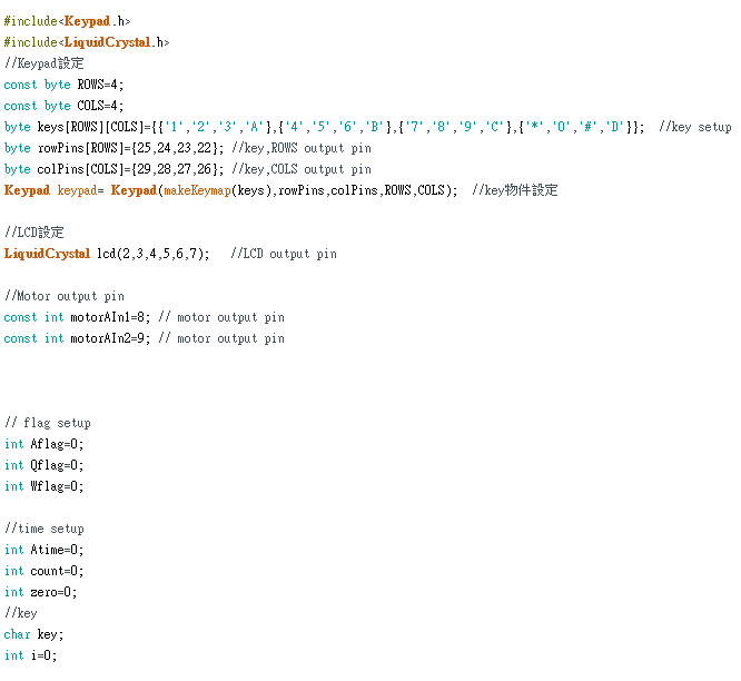
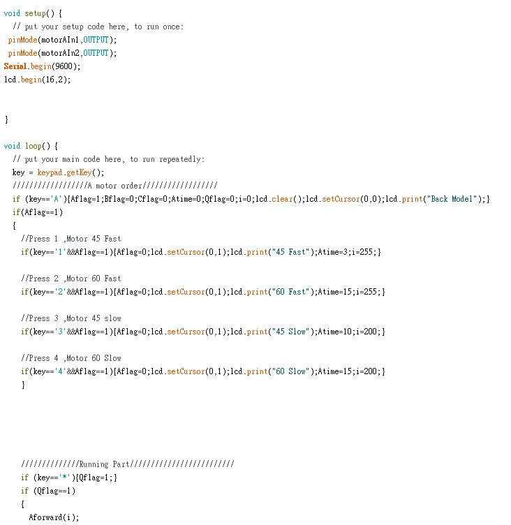
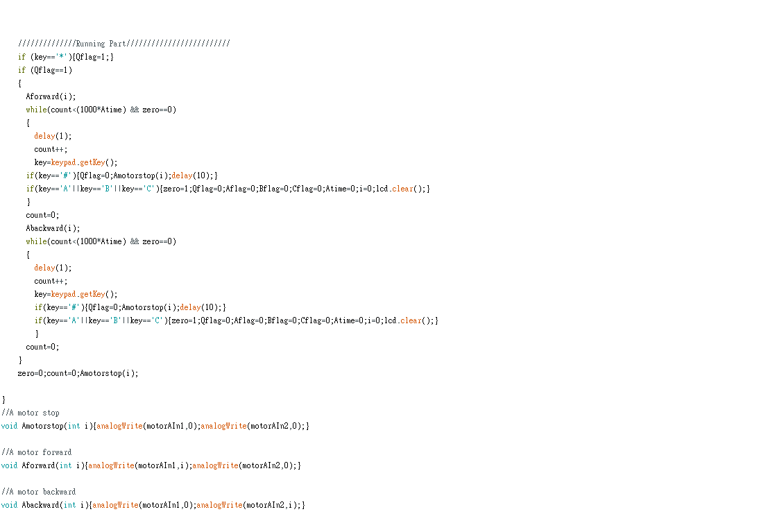
My program is to write the motor up and down.First use L298N drive is OK.But replaced by MC33926, but no output.
Hello.
The Dual MC33926 Motor Driver Carrier and the Jrk 21v3 USB Motor Controller with Feedback use different interfaces and require different control schemes. From the rest of your description, it sounds like you are referring to connecting the dual MC33926 carrier. Are you also using a jrk motor controller?
As explained in the “Basic Application Connections” section of the dual MC33926 carrier’s product page, there is more than one way the board can be controlled (e.g. using two input lines, IN1 and IN2, for direction control and one of the disable lines, D1 or D2, for PWM speed control for each channel, or applying the PWM signal directly to the two input pins with both disable pins held inactive). Also, the default state of the EN pin is low, which puts both motor driver ICs in a low-current sleep mode; if you are connecting 5V to VDD like you metnioned, you can use a jumper to connect the EN pin to the neighboring VDD pin to hold it high and allow the board to run. If you try those things and are still having problems, can you post a wiring diagram or pictures showing how you have it connected?
Brandon

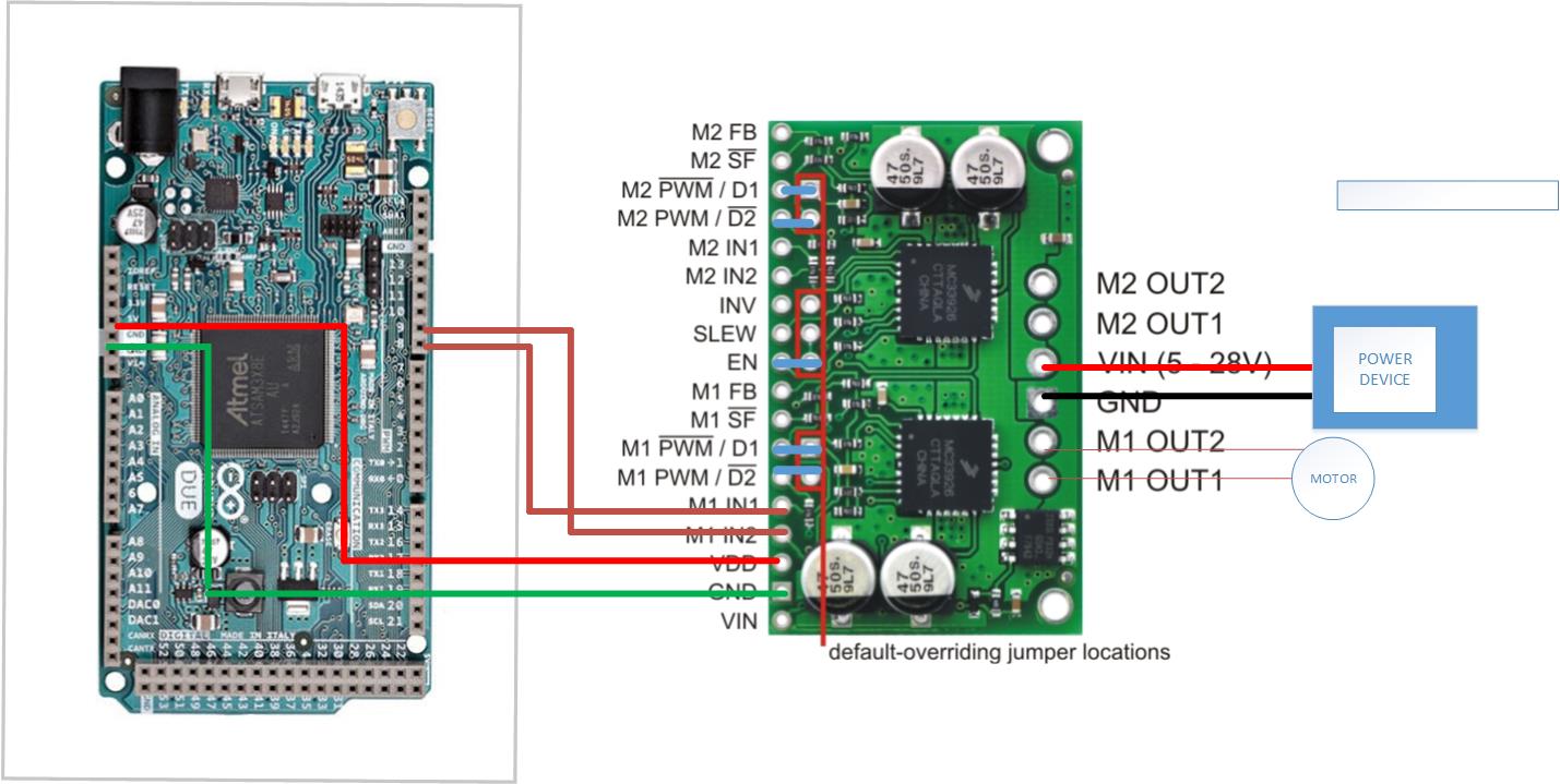
In the first diagram you posted, it does not look like you are doing anything with the D1 and D2 pins, which will disable the board by default. It looks like you are showing the default-overriding jumpers being used in the second diagram, which is correct if you are sending the PWM signals to the IN1 and IN2 pins (and pulling VDD high). Could you post some pictures of your actual setup that show all of your connections? Also, your power supply is just labeled “power device” can you be more specific about what you are using to provide power?
By the way, your code appears to have a lot of extra logic for handling a display and keypad. If you are still having problems getting the driver to run, I recommend simplifying the code down to the minimum required until you get it working.
Brandon