All,
Just recently purchased the Pololu AMIS-30543 Stepper Motor Driver Carrier # 2970 PCB. This is my first stepper project and I have selected the UNO r3 microcontroller interface. Sorry to say that I was not able to bring the hardware online. Can someone help me thru the first few steps to get the hardware at least talking and running, any help would be deeply appreciated.
Thanks in advance,
-eddie
Hello, Eddie.
In an email you sent us about this same issue, you mentioned that the example programs from our library are reporting that “the chip is not active”; can you be more specific about which example program you are running and what message you are getting? Can you post more details about your setup, like how everything is powered and what stepper motor you are using? Also, can you post pictures of your setup that show all of your connections?
Brandon
Hi Brandon,
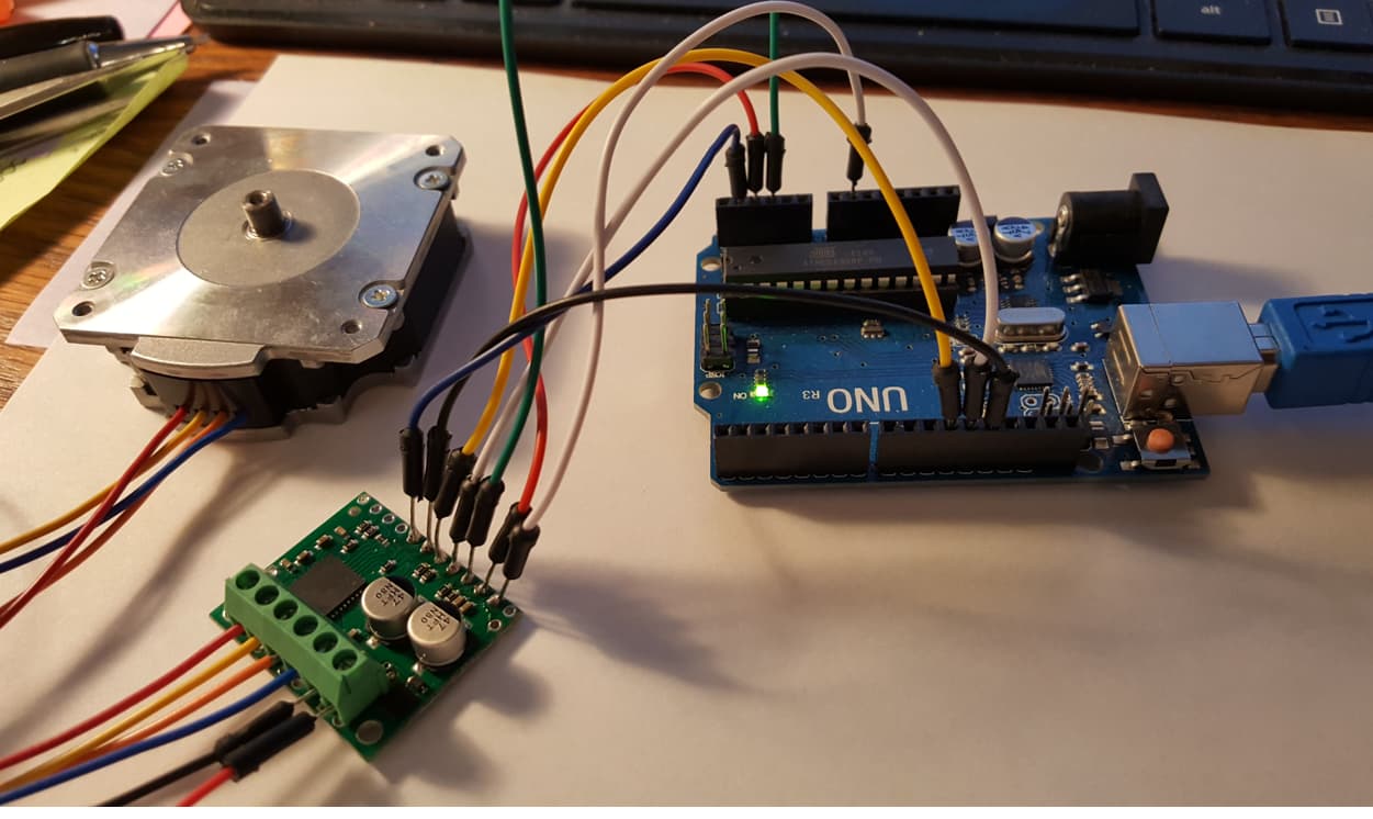
Ok, here the pictures.
-e
Thank you for the additional information.
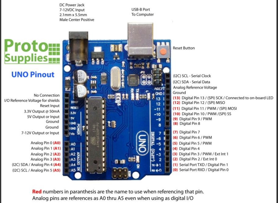
It looks like you are connecting DIR, STEP, and CS from the driver to analog pins A2, A3, and A4 on your Arduino. Our example programs expect the DIR, STEP, and CS pins to be connected to digital pins 2, 3, and 4.
Next, since you are using an Arduino Uno, you should double check that you are sending a 5V signal to the IOREF pin on the AMIS-30543 carrier. You can either do this from your Arduino Uno, or by connecting it to the neighboring VDD pin.
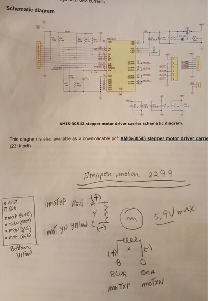
Lastly, you should make sure you are using an adequate motor supply voltage (i.e. something between 6V and 30V that can supply enough current for your stepper motor and any additional devices connected to the system).
Can you try fixing those things and seeing if that helps?
By the way, for future reference, I recommend using header pins, like the ones that came with the board, instead of soldering jumper wires directly to the board. While the latter can make a good connection, it leaves a lot of exposed wire that can easily cause a short and is a lot harder to change later. with female ends, you could also solder female header pins to the board instead.
Brandon
Hi Brandon,
OK, made the wiring corrections on the hardware. Using VDD from AMIS 30543 PCB to IOREF pin.
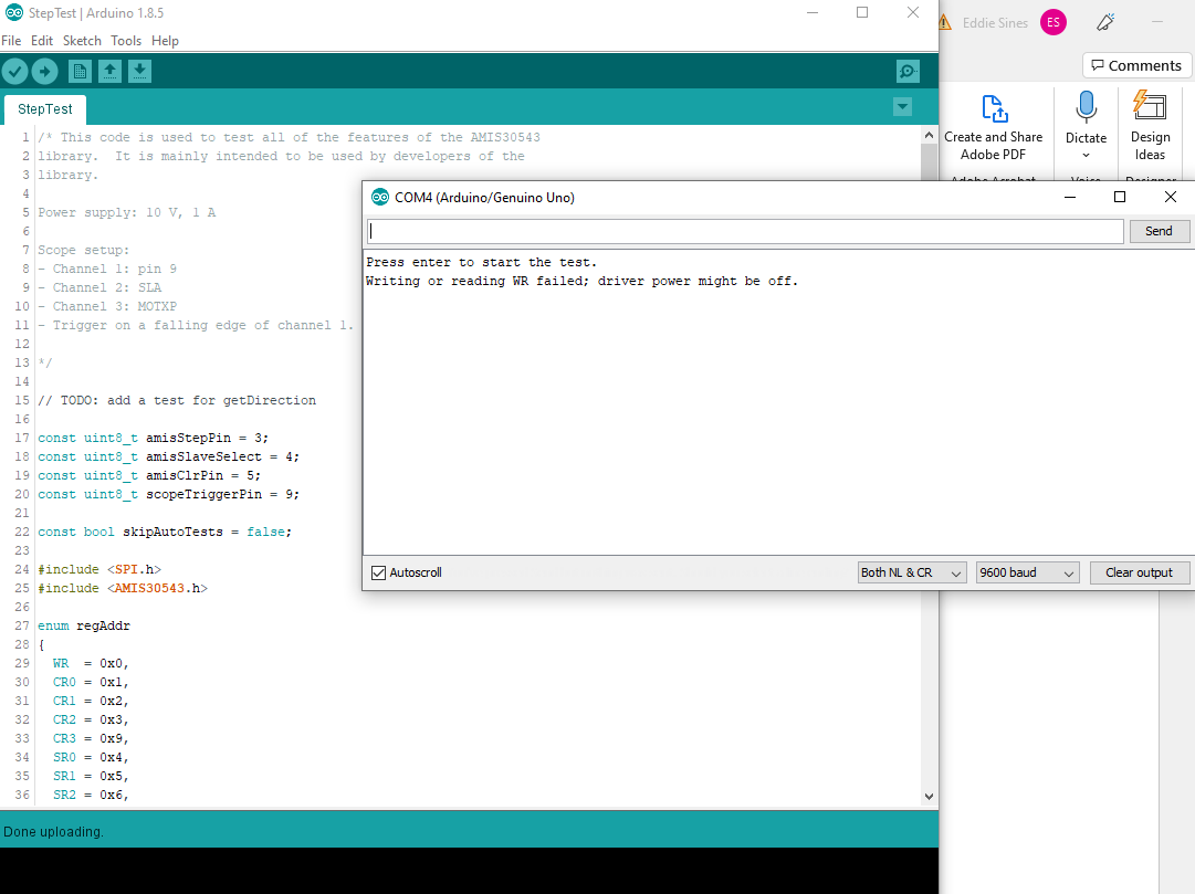
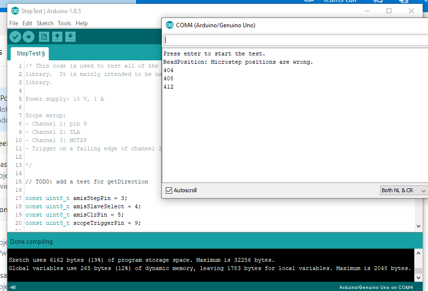
Now the code reports this.
Progress… but the stepper motor still does nothing.
Now I think we’re looking at code?
I need code that basically steps the motor in any direction and steps once a return is entered.
Can you fix this code to do that or send other programs? A simple test is all I need.
-e
StepTest.ino (12.2 KB)
That StepTest example is mainly intended to be used by us for testing the library, but it sounds like the communication is successful now. Can you try running the BasicStepping example and see what happens? Please note that you will need to modify the current limit (i.e. stepper.setCurrentMilliamps(132); on line 46) to something appropriate for your stepper motor. If it is running successfully, that example should alternate between rotating the motor in each direction.
Brandon