
I started testing a stepper using the #2974 module in hopes that its AGC function would reduce the motor’s temperature while it was not in motion but the driver appears to be running at constant current mode; the current holds at the set current value when motion stops. The stepper is a screw type linear actuator so it only needs a low holding current when not moving, and it spends 95% of the time not moving.
I have set the following:
VIN = 12V
Vref =1.08 for 0.6A max motor current
AGC0, 1 = VCC
CLIM0, 1 = GND
DMODE0, 1, 2 = set for full step (LOW, LOW, HIGH)
DFLIM = GND (limit OFF)
LTH = 100K (default value on the module)
BOOST = 100K (default value on the module)
Any suggestions or does the AGC only apply during motion? Normal motion and current are as expected.
Hello.
Can you post some pictures of your setup and tell us about what motor and power supply you are using? What are you setting the current limit to, and how are you measuring the current draw?
- Patrick
Patrick, here is some info and photos as requested.
- The power supply is a Lambda TS150-12. (~12A at 12V) I am only driving one stepper at the moment.
- The motor is a Nanotec LGA201S06-B-TDBA-038 it is a linear actuator - the rotor is essentially a spinning nut that moves a threaded shaft.(0.6A max, I am running it with a 12V supply). The motor has no load.
- The Vref was set to 1.08 for a current limit of ~0.6A. Actual current of ~.6 was verified with a DVM and a Tektronix A6302 non contact DC current probe.


Thank you for the pictures and extra information. Can you try stepping your motor to see if AGC activates when the motor is moving? I would try testing from a few hundred Hz up to 800Hz or so.
Also, can you confirm that all the pins have the right voltage on them with a meter?
- Patrick
Thanks for the help Patrick.
I’m currently running with full steps. The waveform from the current probe shows the set current (0.6A) for each step and that same set current when stepping stops. I had tried different stepping settings (1/8, 1/4) earlier with the same result. I verified all the pin voltages with a meter and also the connection to the IC pins (in case of a cold solder joint). I also have a second board here that acts the same.
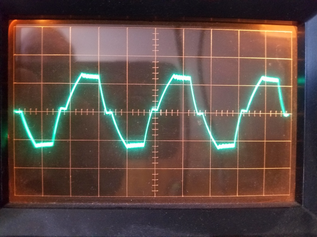
Different pulse rates do not make any difference. The waveform always shows the set current; it looks the same as a non-AGC driver would produce. This photo is at 2.23kHz step rate and 500ma/div. When stepping stops the current sits at the 0.6A set value.
The important thing for me the current after stepping stops. That motor gets up to about 180F while sitting there idle - I was hoping the AGC could help with this.
Unfortunately, Toshiba’s documentation is not very clear about whether AGC is supposed to work when the motor is holding, and it is possible that our documentation is similarly incomplete or misleading (we are currently looking into that). We tested this out with a couple stepper motor here and it appears that AGC generally does not work when the stepper motor is holding or at low step frequencies, possibly due to limitations of the way the driver detects load torque.
In our tests where FLIM was connected to GND, AGC activated around a few hundred Hertz, so I am not sure why it is not activating in your tests with high step rates. One possibility is that your particular motor might need an unusually high step frequency to activate AGC when FLIM is connected to GND; the section about the FLIM pin (page 15) in this application note says:
When connected to GND, the operation is not limited by the limiter circuit of the IC. The induced voltage of the motor, which is used in AGC, is generated by the rotation of the motor. Therefore, the frequency threshold for AGC activation is unique to the motor.
I think that is unlikely, but it would probably be worth testing your driver with FLIM set to something else that fixes the frequency where AGC activates just to eliminate that possibility. Or if you have any different stepper motors, you might test those out to see if you get the same results.
Ultimately though, since your main goal is to reduce the current draw when your motor is holding, you will probably need a different driver. I do not know of any drivers with features similar to AGC that work when the motor is holding. But, we do have several drivers that allow you to dynamically adjust the current limit by sending appropriate signals or using SPI communication:
- DRV8880 (digital signals)
- MP6500 with Digital Current Control (digital or analog signals)
- TB67S128FTG (digital signals)
- AMIS-30543 (SPI)
- Pololu High-Power Stepper Motor Driver 36v4 (SPI)
Alternatively, you might consider one of our Tic Stepper Motor Controllers, make it easy to which control a stepper motor through a variety of high-level control interfaces in addition to their step/dir interface. The USB, TTL serial, and I2C interfaces support dynamically adjusting the current limit.
- Patrick
Good info Patrick. I did try out a NEMA 17 stepper which I set up for a higher Iout current. With this stepperI ws able to see the AGC cut in during motion but as you also observed, the driver pops back up to full current after motion stops. The TB67S looked promising but it turned out to be not quite what I expected. I’ll take a look at the Tic Stepper Motor Controllers and see if they can solve the problem.
Thanks again!