I have been experimenting with an old RC car and the dual MC33926 motor driver carrier and have a few problems/questions. I have read through a bunch of the posts on the forum about this motor driver but still am a little confused on the best way to use it.
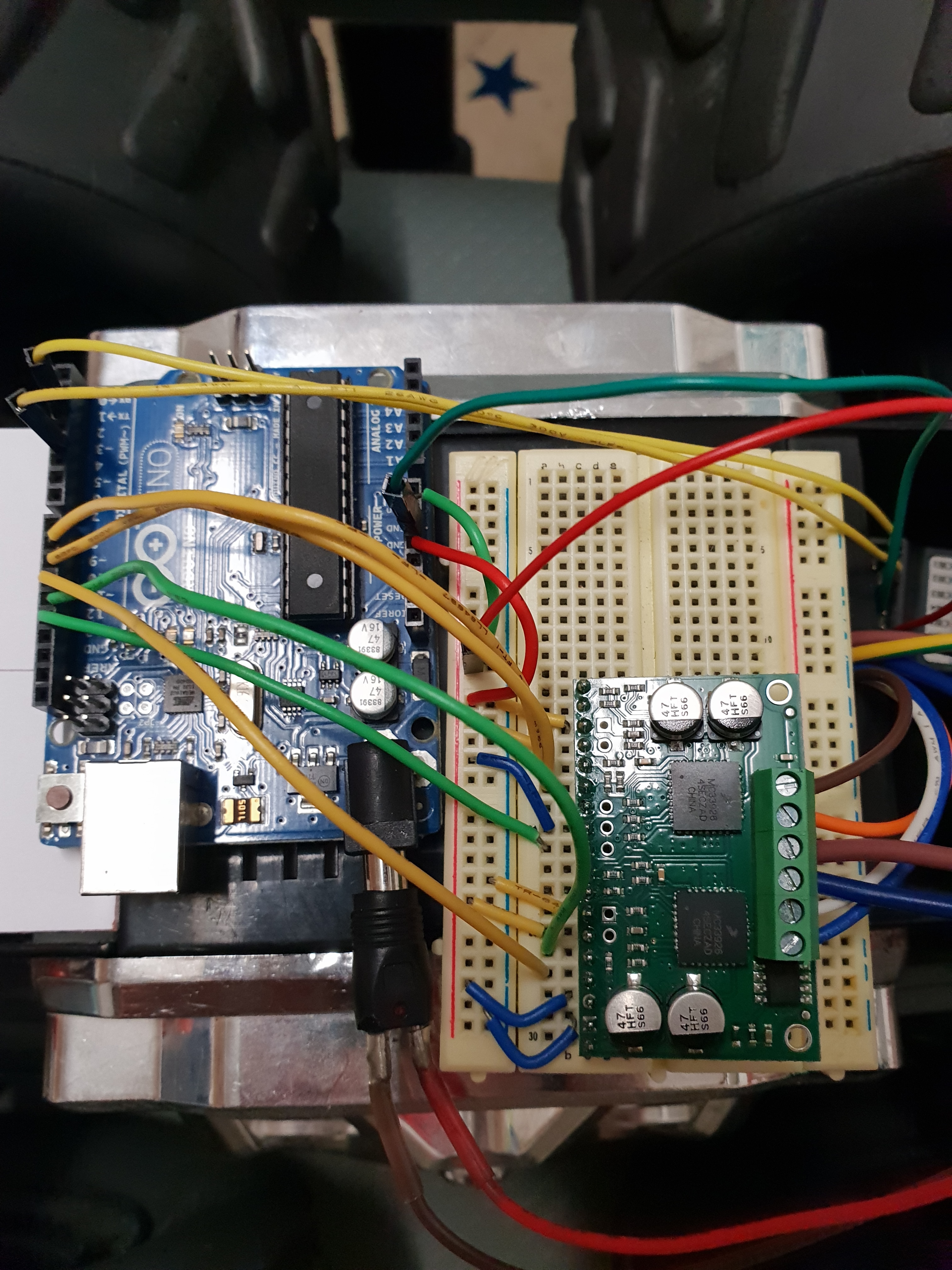
Firstly I connect the motor driver to an Arduino Uno as shown below:
M2 D1 → GND
M2 D2 → +5V
M2 IN1 → Digital Out
M2 IN2 → Analog Out
SLEW → +5V
EN → Digital Out (HIGH)
M1 D1 → GND
M1 D2 → +5V
M1 IN1 → Digital Out
M1 IN2 → Analog Out
VDD → +5V
GND → GND
I was attempting to use the IN1 lines as direction pins for the motor and the IN2 lines for motor speed. However setting the IN1 lines low seems to just stop the motors rather than reverse direction.
Otherwise this setup seems to work ok.
One problem I have is when i set the speed to near max (PWM approaching 255) the motors just stop. I haven’t had a chance to check the state of the status flag yet to see if there is a current problem or anything like that. Does anyone have any ideas??
I would like to be able to reverse the motors and just generally get the most out of this driver board so could anyone please provide a better wiring schematic and simple cases for controlling the motors?
Another thing i noted was when I set the speed to 0, there is a high pitched whine coming from the motors. Is this because the driver is trying to drive the motors at a low speed rather than shutting them off?
Final note: I initially connected the motor power (11.1V) the wrong way around and got a nice puff of smoke and smell… oops. Does seem to still work ok as far as I can tell but maybe some of the logic is fried?
There is no reverse-voltage protection on this board, so if you connected power backwards and saw smoke, it is likely that the driver is damaged. Note that it can be difficult to determine the full extent of the damage from something like this. For example, the driver could be damaged in such a way that the driver appears to work nominally at first, but later the performance could become unreliable and unpredictable, probably worsening with time. I do not recommend using that motor driver.
The behavior you described at maximum speed sounds like the motor driver’s over-temperature or over-current protections, but it difficult to be more certain, since there is a good chance the board has been damaged. If you tell me more about the motors you are trying to control, (i.e. link to a product page or datasheet for them), I might be able to help you verify that this was an appropriate motor driver or help you select a more appropriate one.
By the way, toggling just one of the INx pins will not change the direction of the motor’s rotation. You can learn more about what input conditions are necessary to switch between forward and reverse in the Truth Table (Table 6.) inside the MC33926’s datasheet, which you can find under the Resources tab of the driver’s product page.
Thanks for the reply Jon. I will see if I can find anything out about the motors (this is an RC truck that was given to me without remote).
Just a question, when I have 0 speed, should I set both INx pins to the same and get a “freewheeling” state or set the D2 pin to low and get a high impedance state?
What is the different in terms of the motors behaviour?
The “Free Wheeling Low” and “Free Wheeling High” states are both basically the motor braking (by connecting both outputs to ground or VIN, respectively), which results in an abrupt stop of the motor. Using the disable pin like you described results in a coasting behavior, where power is removed from the motor leads and the motor’s shaft will continue to keep rotating until friction eventually causes it to come to a stop. Which one is most appropriate for you to use will probably depend on the specific details of your application.