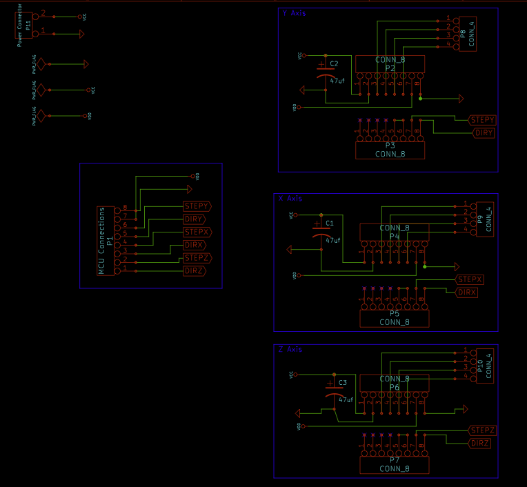
Today I finished up my carrier boards 1 for my CNC and tried giving one stepper motor driver a go.
After connecting it and powering it on (first VDD, then VMOT). I then reset my stepper motor controller which runs it program, nothing is happens. I started to debug and noticed that the voltage on SLP and RST change quite a bit. After reading the resistance on what I think is R3 in the diagram, I get a 125k. I can get the stepper driver to work by manually bringing RST/SLP HIGH from my breadboard.
Now it was previously working in my breadboard setup, but I can’t recall if I manually brought SLP/RST to HIGH or not.
I have another board that I have, but haven’t soldered up headers yet. I’m holding off on testing it as I would rather burn one board than two.
Q1. Could the R3 resistor be bad? 25% seems quite a bit to be out of spec.
Anything else I can test to help figure out the issue?
NOTE I ended up fixing the GND plane connection that is missing from the image by manually making a jumper.
I am sorry you are having trouble with your stepper motor driver. Could you try plugging the driver back into your breadboard, powering it, and then measuring the voltage on the SLP pin to see if it is being pulled up?
Are you sure that the RST and SLP pins are actually lining up with the two pins you have connected together on your PCB? Can you check to make sure that those two pins are not being shorted to anything else? If you just supply power to the motor driver outside of any system, you should see that the SLP pin is at VCC and the RST pin is at 0 V. If this changes when you plug it into your PCB, then your PCB is introducing some (possibly unintended) connections that you should be able to quantify.
I have verified that if I supply power to the board outside of my system I get the results that you suggested.
I have also verified that the RST and SLP pins are connect in my circuit. That capacitor is 100 uF in my circuit instead of the 47 uF, not sure if that will make the difference or not.
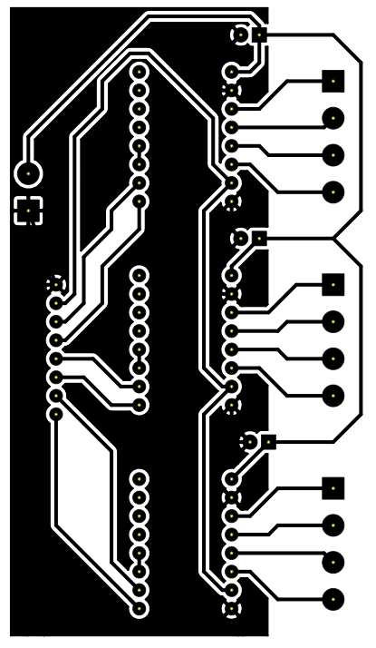
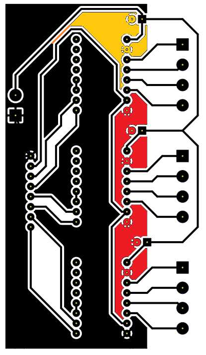
Your PCB layout looks generally okay, except for the ground connections looking somewhat poor. The two parts I’ve colored red aren’t connected to the rest of the ground plane at all, which means that the middle driver will not be grounded unless either the top or bottom driver is populated too (or unless the jumper you referred to in your first post addresses this). In addition, the yellow part of the plane is only connected to the rest by the very thin orange trace; I think it would be a good idea to add a jumper in parallel with this connection.
What do you mean when you say “the voltage on SLP and RST change quite a bit”? What voltage do you actually measure on them? If you can’t get a stable voltage reading, that also suggests a grounding problem. Have you tried checking for good continuity between the driver’s ground pins and your power supply ground? Also, have you tried measuring the voltage on the VDD pin while the driver is in your PCB?
A picture of the populated PCB might help us understand what is going on better.