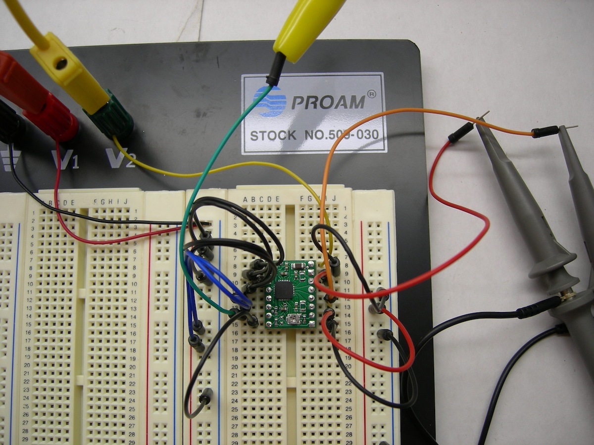
I have been experimenting with the A4988 driver board. Connected as suggested (“minimal wiring” on the website and “A4988 Getting Started” post on this forum) and there is no current to the coils. I am posting a picture of the setup using an ATX PSU and a small stepper from a printer (the connections are correct and I tried other motors as well with the same result). Am I doing something wrong or you guys think I may have received a dud board?
Thanks for your help,
Fabio
Note: the pin headers on the board are soldered below the top of the chip to allow heatsinking experimentation (sic!).
We test all the boards before the ship, so it is unlikely you received a bad board. It’s possible you damaged it by accidentally connecting it wrong, or maybe something about your setup is wrong. Can you verify that you really are supplying the board with motor power and logic power by probing those two pins on the board? What voltages are you connecting to these pins? How did you determine that there is no current in the coils?
I thought that you guys would have pretty good quality control on your boards.
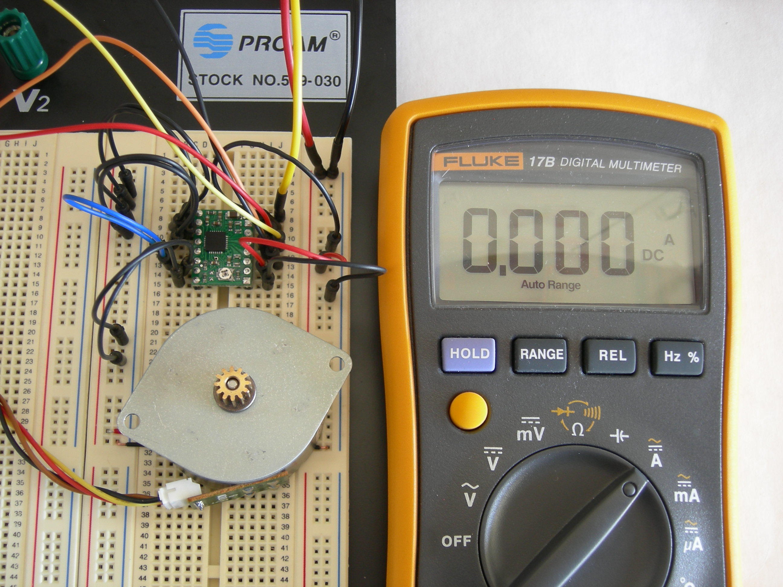
I am using an ATX PSU, so VDD = 5V (red in the picture), VMOT = 12 V (yellow), common ground (blk), and those voltages are measured at the board. I know that there is no current through the coils since the ammeter in series with one of them says 0.00 (also in the picture, and I am prone to trust it). I don’t remember abusing the board (what I described is all I ever got out of it), but even if I am careful , ESD zapping it in a dry day could happen. Any other thoughts?
I don’t see anything wrong in your picture, and there aren’t any obvious problems with your solder joints, so, unfortunately, I don’t really have any other thoughts. I don’t suppose you have a second driver you could test? Please contact us by email with your order information and we’ll see what we can do about a replacement.
Lightening fast reply! Unfortunately, I ordered only one board for testing. I am planning to take advantage of your amazing black Friday discounts and order a new one (among other things), but I won’t refuse a replacement board, if you are so inclined . Shall I just ask customer support?
Thanks again Ben for taking the time to go over this.
FA
Hah, did you just get our newsletter? You can just send an email to www at pololu dot com and reference this thread. Maybe you did get a bad board, or maybe some freak accident killed it, but I still urge you to go over your set-up as carefully as you can with an eye towards anything that might have gone wrong just to help ensure that there isn’t an existing problem that might kill another one.
Is the power supply plugged in and turned on? (I know it is dumb but just double check.)
Did you short the proper pins to allow the power supply to turn on?
Can you plug in another circuit and see if it is properly powered by the ATX power supply?
There is an issue with some ATX power supplies that they need a power resistor on a 5V rail. (Unlikely but possible.)
If none of those things work then upload more photos of your setup.
I agree, it’s always the most stupid mistake that goes undetected. I modded the ATX a few years back by adding a power resistor to the +5V rail (to keep it from going into “no-load shutdown” mode) and a bright LED to the “Motherboard OK” signal, so I can see when it’s actually on. As I mentioned, the supply voltages were measured at the board so, yes, it was powered.
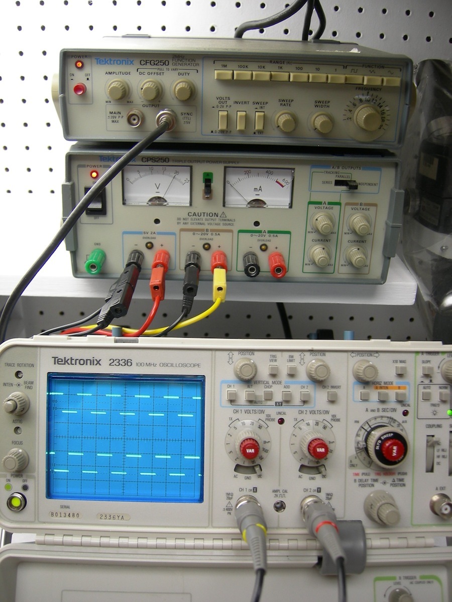
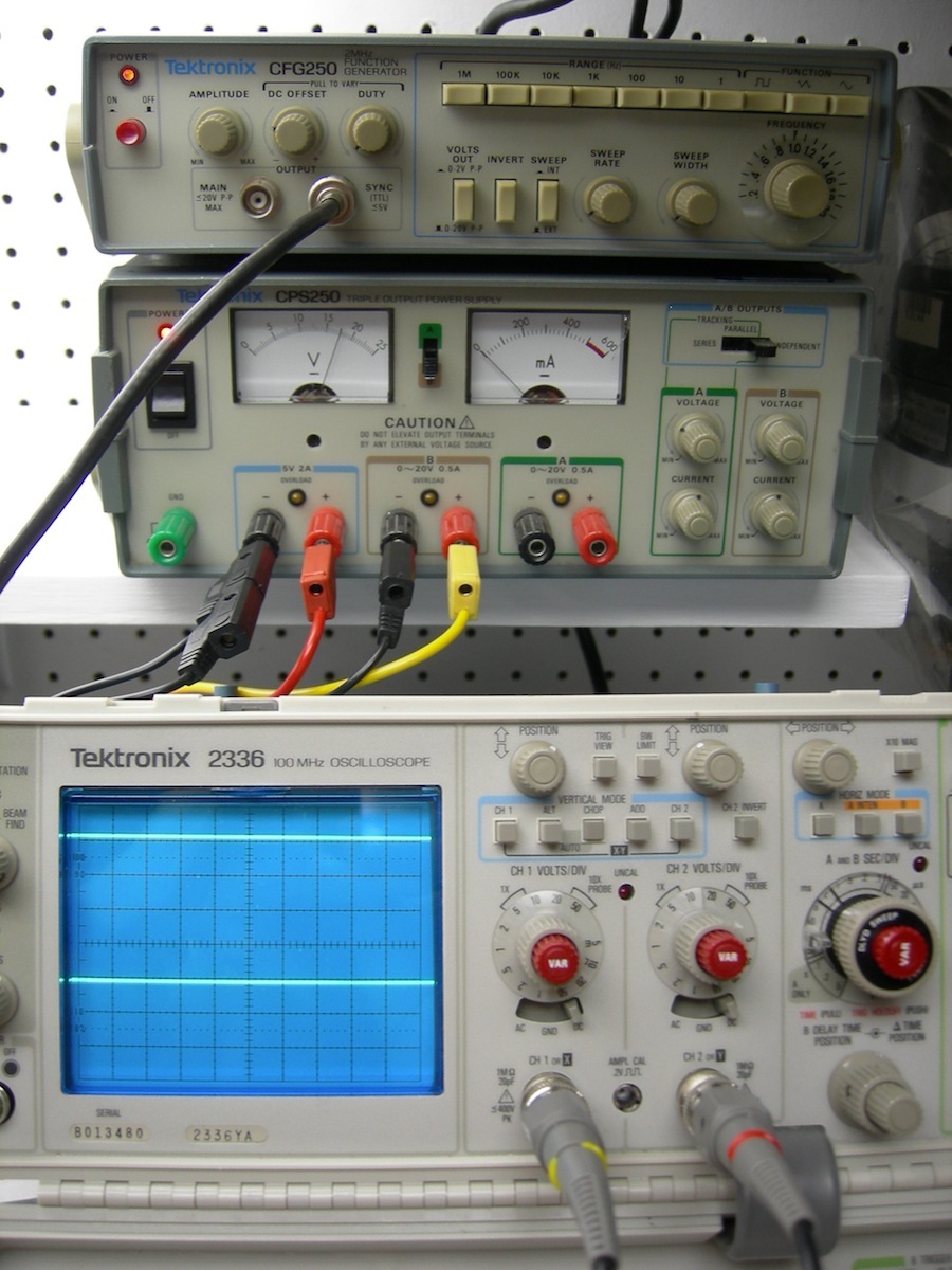
I had time this weekend to play a little more with the board and found some strange results (at least strange to me). My setup is in pic 1. (Note: the green cable with the yellow clip in the middle of the pic comes from the func. gen.):
EN - LOW
MS1 - LOW
MS2 - LOW
MS3 - LOW
RST - HIGH
SLP - HIGH
STEP - 1KHz, 5V pp
DIR - LOW
VMOT - 0-20V var.
GND
2B - open/scope
2A - open/scope
1A - open/scope
1B - open/scope
VDD - 5V
GND
With VMOT at 20V the outputs oscillate with the right shape and phases, but ~5V amplitude (pic 2). The signal is essentially the same with or without the motor connected and insufficient to drive any motor anyway.
If I lower VMOT to ~18V NO output (pic 3).
If RST and SLP are tied to each other NO output; RST needs to be tied HIGH.
As I said, this seems strange to me, but any idea is more than welcome.
I am not sure I can see a ground connection between your function generator and the A4988; do you have such a connection? Also, do you get the same behavior if you try using a lower frequency on the STEP input?
This sounds strange to me; the SLEEP line should be pulled up to VDD by a resistor on the board, and connecting it to RESET should pull that line high as well. Do you measure 5 V on the SLEEP pin with nothing connected to it while the board is powered?
There is a common ground connection, just hiding below the bottom of the picture.
The output frequency follows the step, down to about 20Hz or so.
Kevin you are right: SLP is HIGH.
Exactly what happens is that if RST is already connected to VDD or SLP when the board powers up, the output stays flat (just drifts up to 5V). If RST is brought HIGH with power on the board (either through VDD or SLP), the output oscillates as described.
That behavior definitely sounds unexpected, and I don’t think we’ve noticed anything wrong with your setup, so I will contact you via email to discuss a replacement. (We did receive the email you sent earlier with your order information.)
Wait. You don’t have anything connected to the other side of the coils…
Looking back over the image you have it appears that you just have 1A and 1B hooked up and not 2A or 2B. I am pretty sure that is your problem. You have to allow the current to flow through the coil. (Or in this case your scope setup.)
You say this:
…
2B - open/scope
2A - open/scope
1A - open/scope
1B - open/scope
…
But what I see is this:
…
2B - open
2A - scope
1A - scope
1B - open
…
If it isn’t obvious how to set that up then try connecting an actual motor to the terminals. It should be obvious if the board is working then.
Edit:
After looking back over the pictures I am simply confused.
Simply check your assumptions about how you are simulating the coils that still feels like what is wrong.
Thank you guys for looking over the setup once more.
Kevin: Believe it or not, I’d rather “figure it out” than “throw it out”, but it’s been a lot of hassle for such a little board. A replacement would be a nice touch, but since we cannot determine that it was your fault, strictly speaking you don’t have to.
Ben: The input resistance of an oscilloscope is essentially infinite, so practically no current flows through it and it’s equivalent to an open circuit.
I did connect the motor (same as in my original post) and the signal is essentially the same, just a lot noisier.
At this point, the main motivation for trying to figure it out is to make sure that you aren’t doing something that might destroy any new boards you get. Given that there’s nothing that stands out as wrong, I certainly agree that the easier course is just to try again with a fresh board. Kevin should be contacting you about this soon.
Just to clarify, the post you’re responding to here was made by decrDude, not me.
Yup. Ben is correct. Sorry about that I just was doing a last review over it and thought that the fact that a pair of the wires were disconnected in one of the images was strange. Sorry about that.

 . Shall I just ask customer support?