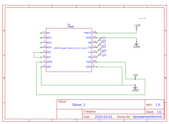
I am having some trouble getting a stepper motor working with the A4988 stepper driver. I have been trying to figure out where the setup is failing. I have isolated the stepper driver for troubleshooting purposes and made connections as shown in the diagram below.
To keep everything as simple as possible, MS1,MS2,MS3, and EN are not used.
The current limiter has been set to 0.6V for the reference voltage (previously working with same motor)
When pin7 STEP is supplied with +5V, pins 11-14 all show +12V
When pin7 STEP is disconnected , pins 11-14 all show 0V
This seems logical and correct. If its not somebody please tell me what I’m doing wrong.
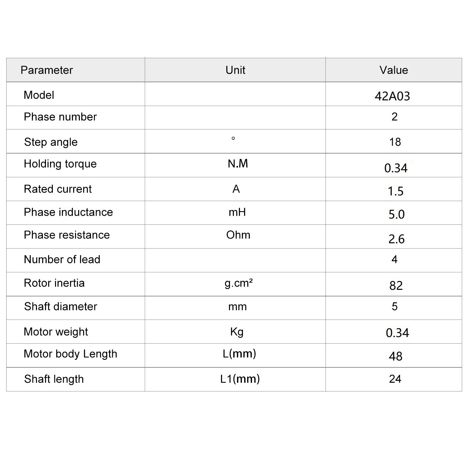
Standard bipolar stepper motor. I have identified the coil pairs by connecting the pairs and observing the motor torque. I have connected the pairs to the 1A/1B and 2A/2B pins respectively. I have measured the voltage as it enters the motor to ensure proper connections and still all 4 pins show +12V.
It is my understanding that with this setup I can intermittently apply +5V to pin7 STEP and I should see/hear/feel something from the motor. However, nothing happens. It is also my understanding that there should be some holding torque present in the motor when pin7 STEP is disconnected. Again, this is not the case.
I’m am out of troubleshooting ideas at this point. I do not know how to further test the motor and I am not positive I have tested the A4988 correctly. Any advice would be much appreciated.
( please note the diagram is missing a 100uF decoupling capacitor on the +12V net )