Hi. I’ve noticed that this question has been asked here and on another forum. I have followed the connection as suggested in your page, double-checked, triple checked to make sure I didn’t miss anything. I’m providing 3.3v from Arduino Uno and 12v from an external power supply to a NEMA 17 stepper motor. Started with your suggested connection but could only get the motor to turn one way. Tried different combination but still can not get the motor to turn both ways. Tried another driver, same result. Does the amount of current play a role in getting the motor to spin both ways? Is GRBL 1 compatible with the driver? I’ve seen in another forum that it’s not. What other information can I provide to clarify the issue.? Thanks for your advise.
Hi.
The direction of the stepper motor is controlled by the DIR pin on the A4988. The current limit setting should not affect this. If multiple drivers are having the same issue, it seem likely there is something wrong in your system. Could you post pictures of your setup that clearly show all connections? Also please clarify whether you are using GRBL code or hardware and link to any relevant specifications or web pages for it.
-Claire
Using Universal Gcode Sender, I’m just jogging the motor manually. For now, I’m just using a breadboard to test and I will provide photos later after work. Thanks Claire.
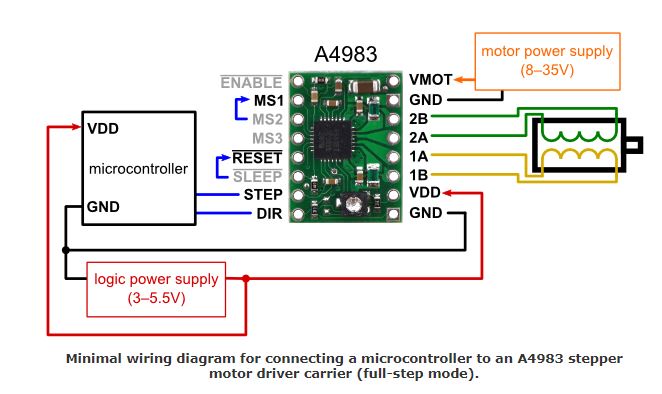
This is the diagram I followed to wire the driver.
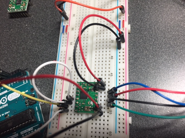
This is how I have it wired. Direction Pin is going to Arduino Uno Pin 4. Step pin is going to Arduino Pin3.
I’m using 12v from PC power supply. and 3.5v from the Arduino.
I switch the 2a and 2b around and it will turn one direction. I’ve made sure there is continuity on from the Direction pin to the end of the wire before the Arduino.
Is there anything else I should try?
You mentioned powering VDD from 3.5V (I suspect you meant 3.3V) with the Arduino, but the logic signals that Arduino Unos send are 5V, so you should power VDD with 5V as well. Looking at the A4988’s datasheet it seems like that is probably okay, but please note that for many other ICs it is possible to damage digital pins or the whole chip if they are supplied with signals of higher voltage than their power input.
Other than that I do not see anything wrong from the picture.
“I switch the 2a and 2b around and it will turn one direction.”
To clarify, when you switched those motor wires did the motor change direction?
Could you try connecting the DIR pin directly to GND and 5V and see if that helps?
-Claire
When I connect 2a and 2b so they are in order the motor turns one direction. When I switch them around the motor turns the opposite direction.
"Could you try connecting the DIR pin directly to GND and 5V and see if that helps?"
I’m not sure what you want me to do here. You wanted me to connect DIR pin from the pololu to both GND and 5V?
Please try connecting DIR directly to GND and see what direction the motor turns. Then remove the connection to GND and connect DIR directly to 5V instead and see if it turns the same way or the other way.
-Claire
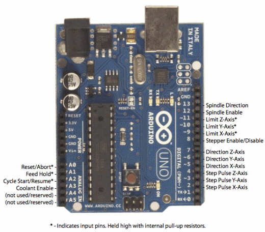
Thanks for trying to help Claire. I figured out what’s wrong. It’s a newbie mistake on my part. For those who might be in the same boat and are just starting to learn, here’s the photo that helped me.
Turns out I had the DIR pin connected to PIN 4 on Arduino which is Step Pulse Z-Axis instead of PIN 5. I somehow saw another photo from another page that instructed me to connect DIR and STEP to 3 and 4.