I’ve read through some of the other posts on this board and the general tips/FAQ sticky, but I’m still having some problems with my stepper motor.
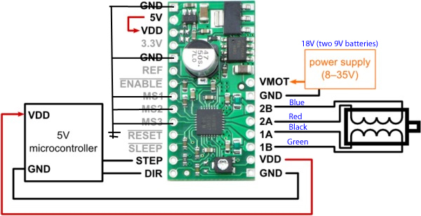
I am using the A4988 motor controller, a stepper motor from this site (7.4V, 280mA 26ohm per coil), and an Atmega16 chip. I have things wired up as shown in the example picture (I am using the 5vdc output to power the Atmega16). I’ve attached a picture of my set up just for reference (basically just pulling M1-M3 to ground for full step mode, DIR pulled to ground for constant direction).
The code that I have written is very simple (where port 5 is the input from my controller to STEP on the A4988):
		PORT_ON(PORTD, 5);
		delay_cycles(1000);
		PORT_OFF(PORTD,5);
		delay_cycles(10);
Nothing else is going on on my code, clock cycles are set such that the chip is running at 1mhz. I have tried two power supplies and array of 9v batteries and an industrial grade lab power supply at 24v, both produce the same results. The motor will twitch, hum, and sometimes begin to rotate. But the torque output is zero, motor will stop turning on it’s own or the second I barely touch the shaft with my finger. I set the max current to the coils using the Vref method, using the equation in the A4988 data sheet I got:
0.280 = Vref / (8 x 0.05)
So, Vref setpoint comes to be Vref=0.112v
Based on my understanding of how the to set the pot on the chip, this should be right. I’ve worked with the Atmega16 quite a bit before, so I’m quite confident that I am sending the waveform that I have programmed and it should be in an ok spot on the motor torque vs pps plot. Any help or advice would be greatly appreciated!
EDIT: Removing the connections from M1-M3 to ground have no effect on performance, I just tried that out. Seems like if you let them float it defaults to full step?