
Taking in an automotive tach input and running a stepper motor based on this value (Think tachometer) and we are having a weird issue where the board will randomly step even though the arduino isn’t telling it to. Oscilloscope shows no change in any pins except for the outputs to the stepper. We set the arduino pro-mini to move the stepper a little every couple seconds to make sure it works then stop and hold position. When the stepper is holding position if we increase or decrease the rpm quickly the a4988 will move the stepper all over the place in different directions and speeds. This tach input is a really noisy signal and we noticed putting the board on the standoffs helps a lot but doesn’t completely cure it. oscilloscope all the other pins show a solid 5v(on logic pins), 12v on power in, and ground pins don’t blip. Anything we can do to help with the noise? The tach input is on the opposite side of the pcb board and doesn’t have any leads near the a4988 and is run through a filtering circuit before it goes into the arduino. RPM reads very cleanly.
Hi.
Could you post some pictures of the system? Is the system inside a car engine or supplied by the 12V battery of a car? Some scope captures of the noise on the output and a video of the behavior might also be helpful.
-Claire
Yes we are running off the cars battery and grounded directly to the block and the battery.
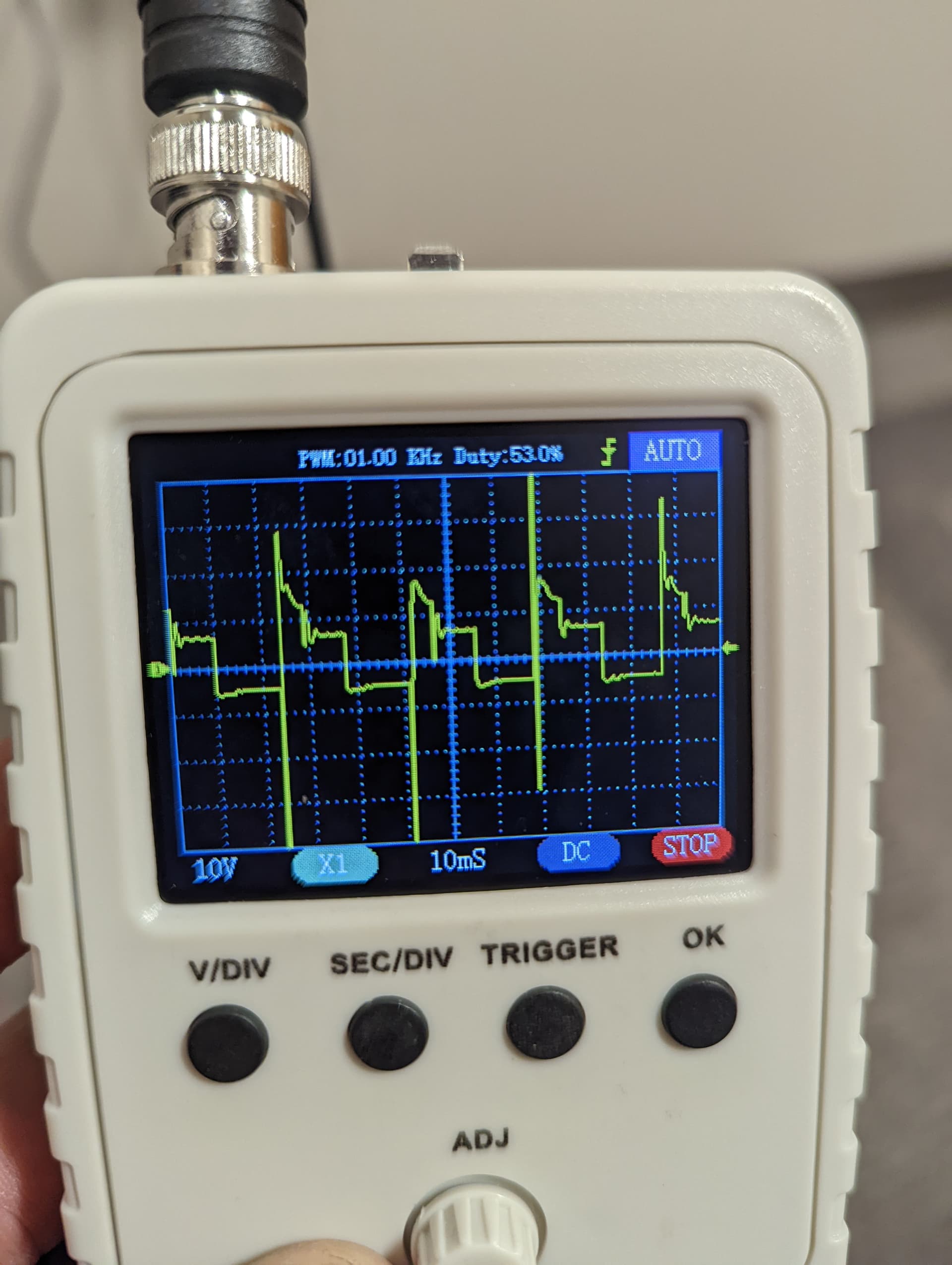
Here’s a pic of the input tach signal coming in
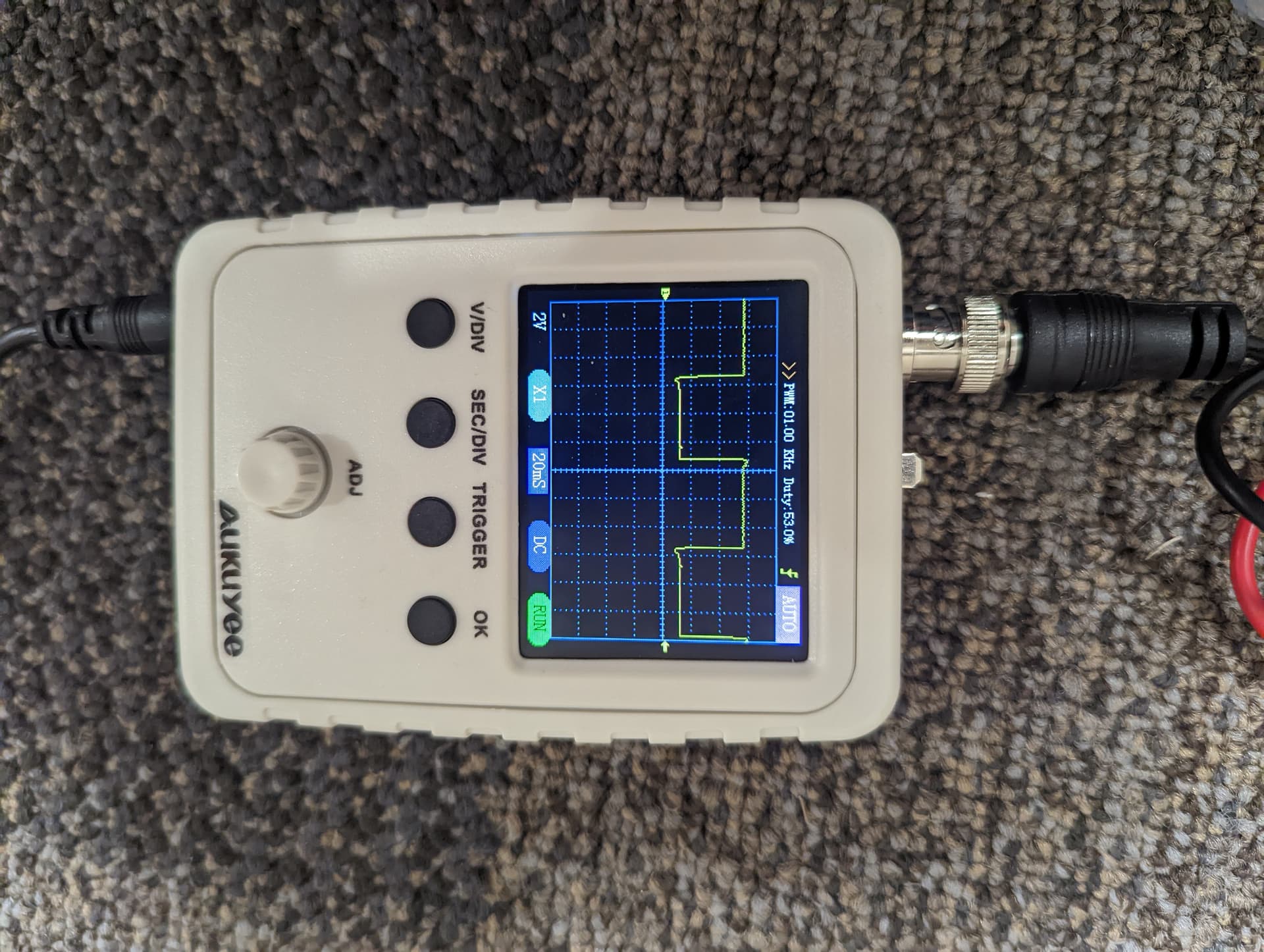
Here’s what we got it cleaned up to.
This goes into the Arduino pro mini then on the opposite side of the arduino it gets the step and direction values. If we unhook the tach from the board it stops the random jumps.
Is the car’s engine running during your test? If so does the noise go away when the engine is off? Could you post a connection diagram and pictures of the setup?
-Claire
The car must be running to get tachometer signal in. It is the signal that says what RPM the engine is running at.
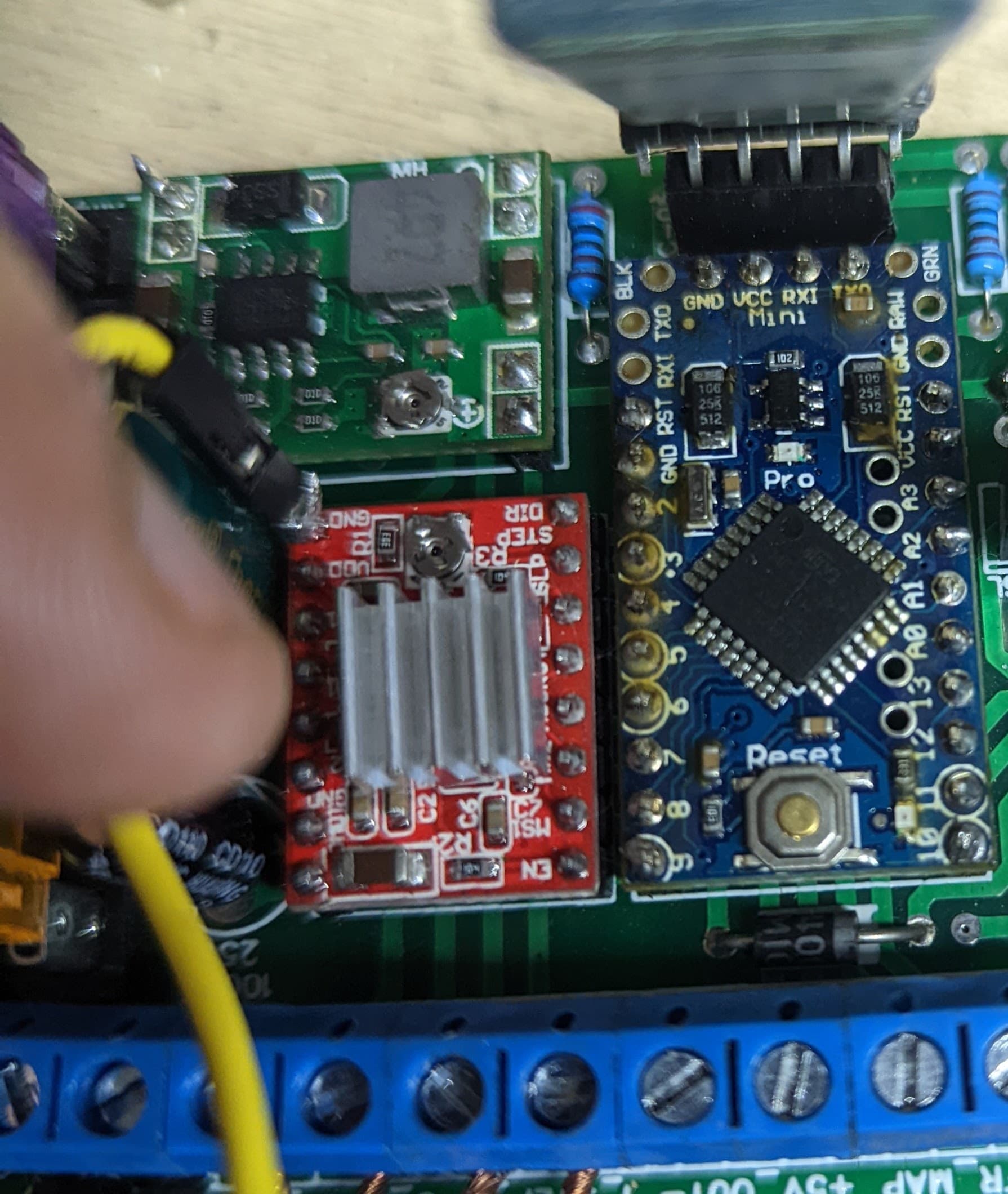
Here is the best picture I have of the setup, ignore the extra ground wire added, we did that to verify that grounding wasn’t the issue. The circuit for the incoming tach is right of the Arduino and that circuit is just a simple low pass filter with a transistor to input the signal into the Arduino.
It is hard to see how things are connected in your picture. If you post a wiring diagram I would be happy to look through, but given that a car engine is involved, I highly suspect the issue is EMI. Car engines can be incredibly electrically noisy, so my recommendation is to isolate the microcontroller and stepper motor from the engine as much as possible (though it looks like that might require a lot of redesigning). You could start by trying to power your electronics from a separate battery instead of the car’s electrical system and shielding the electronics to see if that helps at all. You might also try looking into noise mitigation techniques that car audio hobbyists use.
-Claire