I wound up a spring using my stepper, and then brought the enable pin high to coast the stepper and spring back to the spring’s home position. this spun the stepper pretty fast, which would cause quite the spike, I would imagine. However, I have a 100μF cap on my VMOT-GNDMOT lines, so I figured I would be safe. This is apparently not the case, as my logic power and ground pins are now common. 6 of my 7 USB ports stop working at the same time, an unlikely coincidence. The USB was just powering my Arduino, which was in turn feeding logic voltage to the A4988, but the Arduino is totally fine.
Was this failure my fault? How can avoid it in the future? I have a spare A4988, but I would like to make sure I won’t repeat my mistake. My next plan of action is to PWM the enable line to prevent the motor from spinning quite so fast. Will this work?
My PWM technique was ineffective. The stepper didn’t have enough torque to stop the accelerating spring. Me spare A4988 actually caught fire on this attempt. I guess I better order some more.
First, the alligator clips in your setup make us uneasy. Alligator clips can cause intermittent connections, and disconnecting a stepper motor, even for a couple microseconds, when it is powered can damage it. Also, because your clips do not have insulation they could easily be shorted together.
However, it is more likely that manually spinning your stepper motor generated back EMF larger than the A4988’s 35V limit, which damaged the boards. Putting an electrolytic capacitor across GND and VMOT should suppress short spikes, but it would have to be really big to absorb that energy without the voltage rising much. Is it an option for you to step the motor back to its home position rather than use a spring?
Just to rule out any possible connection issues, could you detail all of your connections? How are you powering everything?
If you haven’t already, can you try rebooting your computer to see if that fixes the USB ports? Computers often shut down misbehaving USB ports for protection.
I am aware of the shortcomings of alligator clips, however I ensured that they wouldn’t short together, and that their connections where very good. I inspected all my connections before each test, and removed power from the entire system when I wasn’t running it. None of them could be jostled, all of my buttons were on a separate board.
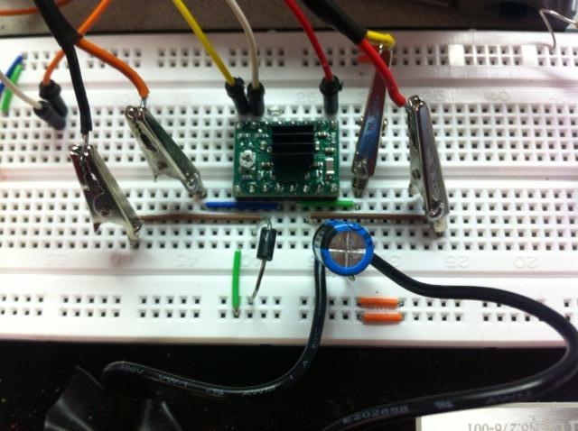
Connections:
15V power supply to a screw connector, wire coming from that to VMOT
Ground from the 15V supply the same way
Arduino 5V and GND to VDD and it’s GND.
The 5V has a power diode on it, a vestige from when I was using an under-rated dual-H-bridge to drive my stepper, which also failed catastrophically.
The Arduino receives it’s power from USB.
I did not tie logic GND to VMOT GND because they aren’t common on the board, I figured they were intentionally isolated.
There is a 100μF 35v electrolytic capacitor from VMOT to GND.
I have data lines from the Arduino running to DIR, STEP, and ENABLE.
I have a small heat sink on my driver, as my stepper draws 1.75A peak.
I know the wires running to the stepper coils are in the right order, everything works great until the motor is wound up.
I can try and step down to home, I overnighted 3 more drivers from your amazon store, they should be here in the next few hours. I will have to change other parts of my design, but if that’s the only way to save my drivers, that’s more than fine.
Your connections seem fine (note that logical ground and motor ground are connected on the board). However, I suggest replacing your capacitor, since the supply voltage likely exceeded 35V when your previous boards were damaged, which could have damaged the capacitor as well. Also, I still recommend stepping the motor down, but it is not the only solution; something like a 25V transient voltage suppressor (TVS) could be used to protect your existing system.
Please let me know how it goes with the new boards!
A Transient Voltage Suppressor (TVS) is a specialized type of zener diode, so, given that you will be using the diode for transient suppression, it would probably be better to use a TVS. However, if you have a zener diode that can handle the voltage and current you are expecting, it might be fine. Varistors are probably not good for this application because they are not intended for repeated transients, and the voltage you are using is relatively low compared to their usual clamping voltages.
Also, all of the devices you listed are generally connected across power and ground.
I see – Hammerstein exited the thread, and Zapnologica jumped in the thread. Happerstein had the 15V supply
TVS-es are good, and as long as the rated breakdown voltage is higher than your supply voltage, then they should be fine.
The TVS-es you listed are fine, assuming they are for the right voltage (the part number maps to a large range of voltages.)
As jwatte said, you will need a TVS that will not conduct at your highest possible supply voltage, but will be sure to clamp below the drivers maximum of 35V. So, the one you proposed, which has a minimum breakdown voltage of 15.2V, is definitely not suitable.