Hello,
I’m a relative newbie in electronics.
Here are my questions pertaining to decay mode selection for
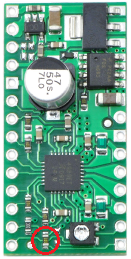
- A4988 driver pololu.com/product/1183
- Allegro documentation pololu.com/file/download/a49 … e_id=0J450
On page 7, the Allegro documentation says:
“By pulling the ROSC pin to ground, mixed decay is set to be active 100% of the time, for both rising and falling currents, and prevents missed steps as shown in figure 2”
My question:
The schematic for the carrier board shows ROSC (pin 13) grounded via R4 (10k).
Am I correctly understanding that this board is hardwired to automatic decay mode selection (slow decay periods are present)?
And that Toff = ROSC/825 implies a fixed Toff of 12 uS?
In order to achieve mixed decay 100% of the time (no exclusively slow decay cycles) and avoid missed steps described in figure 2, the suggested approach is to wire OSC directly to ground bypassing R4 completely?
Is it possible to do this mod ‘in the field’ with a regular soldering iron?
Thank you for the response!
Ron