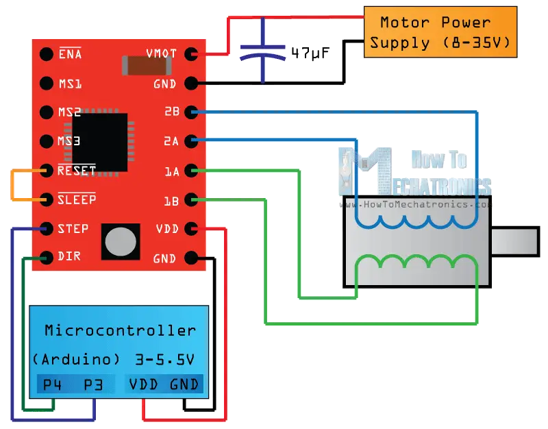
I am using the A4988 driver to drive a 42BYGHW811 NEMA-17 bi-polar stepper motor. My schematic is http://howtomechatronics.com/wp-content/uploads/2015/08/A4988-Wiring-Diagram.png
The first time I tested it, it was able to rotate CCW and CW. However, I swapped out the driver with another A4988 and the new driver would only rotate when the direction pin was logic LOW. For logic high it would just buzz. I then switched it back to the original driver and it had the same problem of buzzing instead of moving when the direction pin is HIGH.
I have tried arranging the wire pairs in all 8 configurations and while that would change the direction it rotates the stepper will only rotate when the direction pin is LOW.
Any help would be appreciated!
Hello.
Did you set the current limit and, if so, what is the VREF voltage on your drivers? Can you post pictures that show both of your drivers, their soldered joints, and all of the connections in your setup?
-Nathan
The Vref on both is .5V which I believe limits the current to 1A.
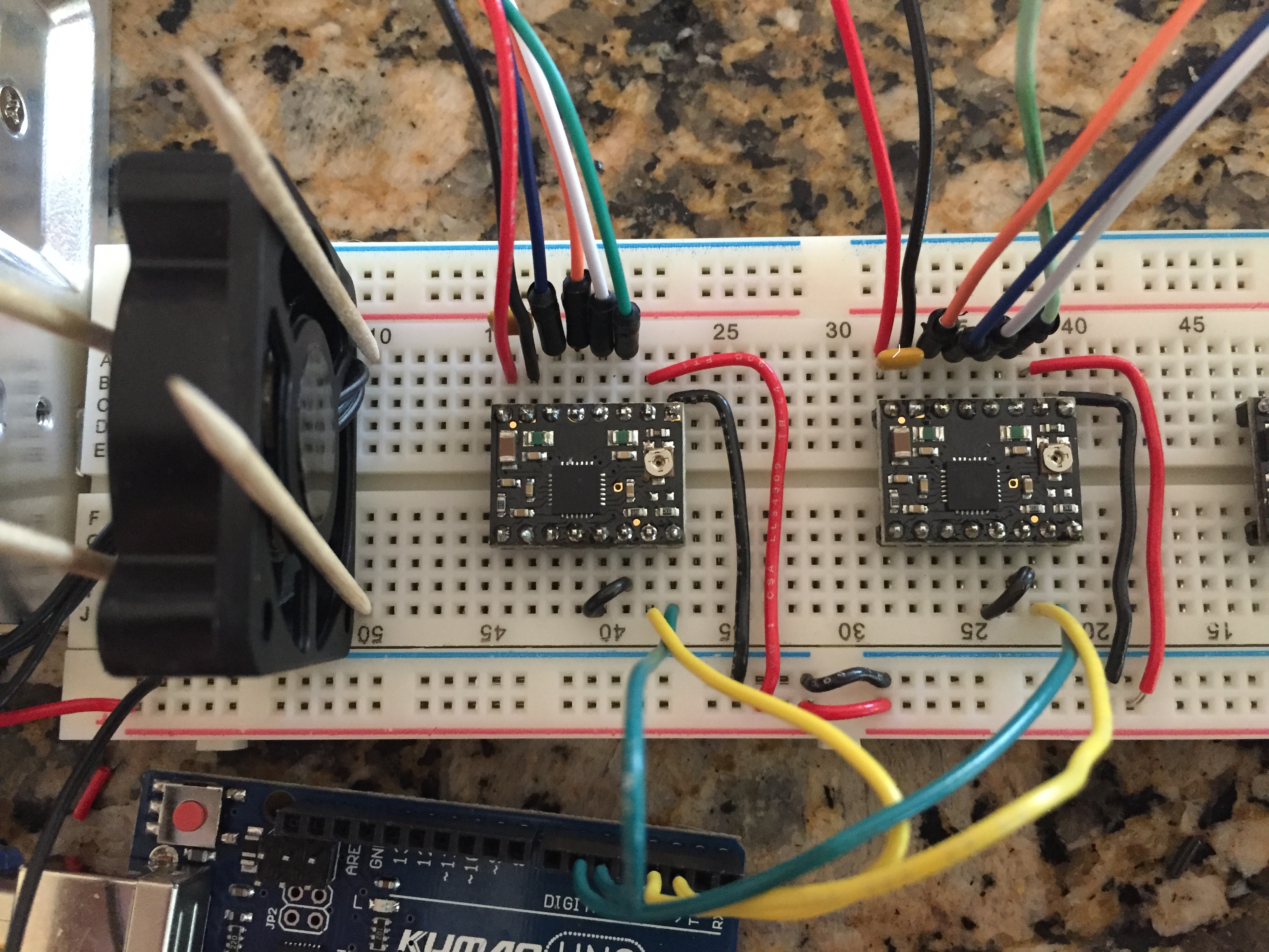
Here is my setup up testing both drivers:
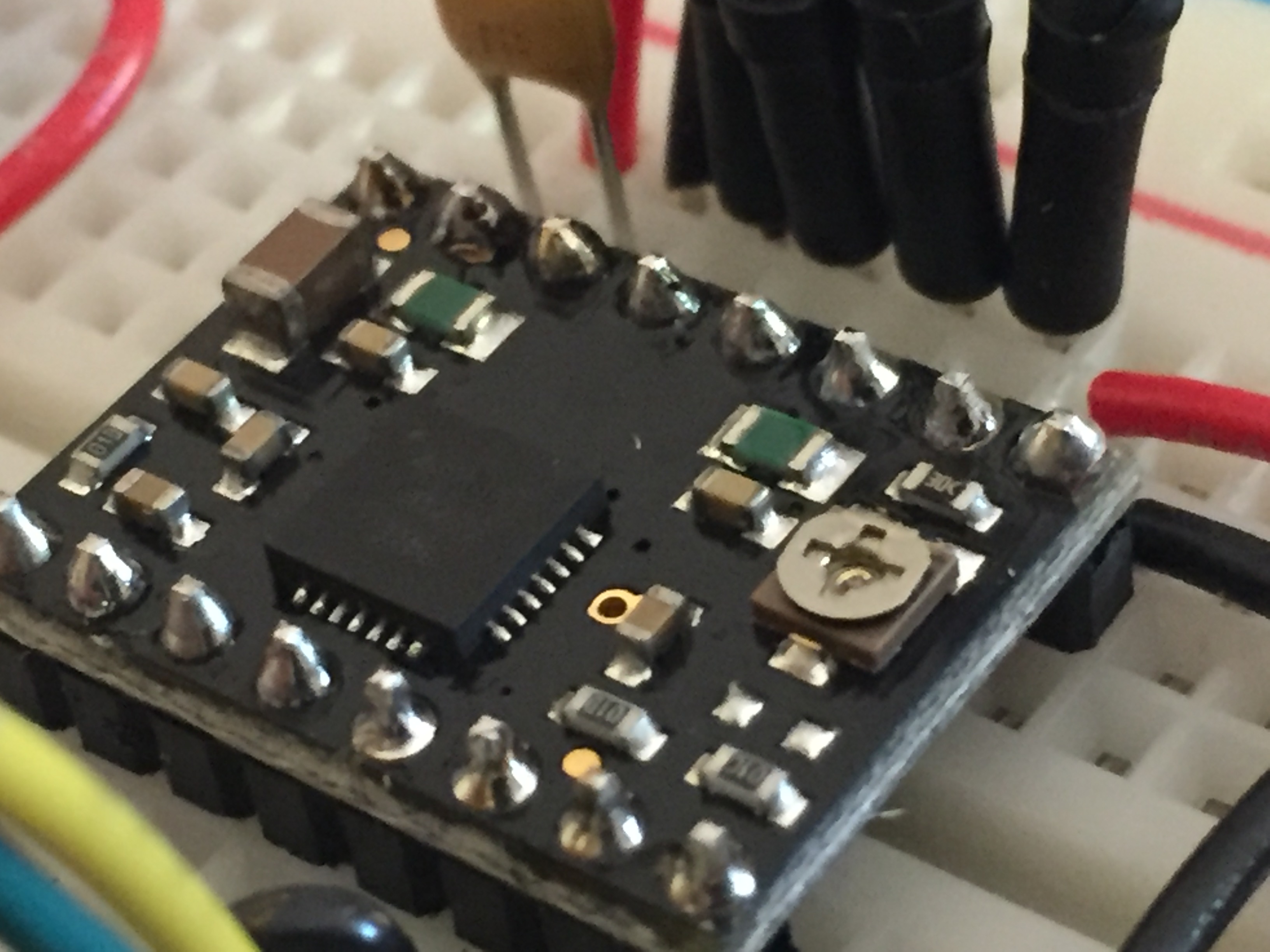
Close up of the solder joints for both drivers:
and this is the Arduino Code I am using to test functionality:
const int stepX = 2;
const int dirX = 5;

const int stepY = 3;
const int dirY = 6;

const int wait = 10000;

void setup() {
  // Sets the  pins as Outputs
  pinMode(stepX,OUTPUT);
  pinMode(dirX,OUTPUT);

  pinMode(stepY,OUTPUT);
  pinMode(dirY,OUTPUT);

}
void loop() {


  digitalWrite(dirX,HIGH); // Enables the motor to move in a particular direction
  digitalWrite(dirY,HIGH); // Enables the motor to move in a particular direction

  // Makes 200 pulses for making one full cycle rotation
  for(int x = 0; x < 200; x++) {

    digitalWrite(stepX,HIGH);
    digitalWrite(stepY,HIGH);

    delayMicroseconds(wait);

    digitalWrite(stepX,LOW);
    digitalWrite(stepY,LOW);

    delayMicroseconds(wait);
  }
  delay(1000); // One second delay

  digitalWrite(dirX,LOW); //Changes the rotations direction
  digitalWrite(dirY,LOW); //Changes the rotations direction

  // Makes 400 pulses for making two full cycle rotation
  for(int x = 0; x < 400; x++) {

    digitalWrite(stepX,HIGH);
    digitalWrite(stepY,HIGH);

    delayMicroseconds(wait);

    digitalWrite(stepX,LOW);
    digitalWrite(stepY,LOW);

    delayMicroseconds(wait);
  }
  delay(1000);
}
Thanks for posting those pictures. I do not see any obvious problems with your connections. Do you have anything on the motor shaft? Have you tried different speeds or microstepping? Mechanical resonance can cause problems sometimes and adding some rotational inertia to the shafts, using microstepping to smooth the motion, and using a different step frequency can help.
It seems like you are using the wrong formula for the current limit. It looks like your boards use 0.05 ohm current sense resistors, so 0.5V is 1.25A. You can find the formula to calculate the Vref for a current limit using the current sense resistor value on the product page for the A4988 boards.
Also, it looks like you are using ceramic capacitors rather than electrolytic capacitors at the motor power supply. Ceramic capacitors there are not really going to prevent LC spikes and might actually make them worse.
-Nathan
Speeding up the pulse rate and switching to 8th steps did the trick!.
Thanks for you help Nathan!

