A4988 doesn't microstep properly

Hi,

I have a 2.5A 3.1V motor. I have a 12V powersupply, and inbetween those is an A4988 stepper driver from Pololu.

I’ve been testing my software, and I’m able to make the motor run say 1 rotation or 10 rotations. No problem. But the motor vibrates a bit more than what I’d expect from a microstepping driver. So now I’m investigating, and when I issue one microstep at a time, 15 of them result in a very small “tick” on the axis. I can’t be sure if it actually moves. Then on the 16th step the motor moves a really significant amount.

I’ve set the current limit voltage Vref at 0.37V for a current limit of almost 1A. I then found the A4988 to run too hot for my taste, so I’ve turned it back down again a bit.

My Microprocessor is an STM32F4 board. It runs at 3.0V. Hmm. OK. When I measure the 3.0V powersupply it comes to about 2.96V. The A4988 datasheet mentions a minimum of 3.0. So I’m off to solder a 3.3V regulator on my board. But I don’t expect that to change anything.

Any suggestions?

Update: The LM1085 has a dropout of 1.3V. Should JUST be enough for the 5V to 3.3V, right? Nope: the 5V on the STM32F4 board is only 4.5V because it has a series diode. My SPX1117 goes in current limit at 1.4V or something like that. The A4988 becomes hot. OK. New Pololu board, seems to leave the power at the intended value.

Update2: The Pololu now runs at 5V, same issue.

Update3: I’ve measured the steps: they start out really really small, then become slightly larger before the big step. Then they start out really small again. Watch it for yourself: prive.bitwizard.nl/MOV05295.MPG

Hi.

Thank you for posting the video; the laser dot was a great idea to illustrate the issue. Could you tell me what microstepping mode are you in? What is the behavior like in different step modes? Does the motor behave the same way when turning in the other direction? If you turn the motor shaft by hand does the motor have particularly strong cogging (i.e. how strongly does it try to jump to set positions as you turn it)? Could you please post your code? Also, do you have a smaller stepper motor you could try and see if the results are similar?

-Derrill

I’m in 1/16th stepping mode. I’ve soldered the MSx pins to VCC because that’s what I want. I didn’t think I’d ever want anything else. It is kind of a hassle to tear them loose and make it configurable. I have .2mm per fullstep on my machine. I really need a better resolution than that, so I’ve decided to use the 1/16th microstepping mode. If I don’t achieve the 0.0125mm reproducability, that’s ok. But better than 0.2mm would be very welcome. I can probably survive on 0.1mm at halfsteps…

I have the impression that when I reverse direction, it will almost immediately do the “big” step and then the sequence of smaller steps. But this could be because of my “positioning” in the cycle of 16 microsteps.

The motor has some cogging, especially when it is powered. (but I’m guessing you didn’t ask for that). I have a stepper from an IBM printer that has stronger cogging than the steppers for my machine.

The code is quite elaborate already.

Here is the code to send a pulse:

static void send_pulse (int direction, int dirmask, int stepmask) 
{
  if (direction) gpio_set   (GPIOD, dirmask);
  else           gpio_clear (GPIOD, dirmask);

  for (t=0;t<14;t++) // wait 200ns. 8 is enough?
    __asm__ ("  nop");

  gpio_set (GPIOD, stepmask);
  delayus (1);
  gpio_clear (GPIOD, stepmask);
}

My step and direction pins are located in gpio port D. The delays are neccessary to observe the timings for the A4988 chip. The 1 microsecond minimum pulse width is unfortunate: I now have to have a busywaiting loop inside the interrupt routine. On the other hand, the chip handles a 100ns pulse just fine as well, but I’m not risking it until everything works as advertized…

static void do_steps (struct state *p)
{
  if (p->steps > 0) {
    p->v += p->a; // process "accelleration". 
    p->fpos += p->v; // process "speed". 

    while (p->fpos >= 0x01000000) {
      send_pulse (1, p->dirmask, p->stepmask);
      p->fpos -= 0x01000000;
      p->pos++;
    }
    
    while (p->fpos < 0) {
      send_pulse (0, p->dirmask, p->stepmask);
      p->fpos += 0x01000000;
      p->pos--;
    }
    p->steps--;
    gpio_set (GPIOD, p->ledmask);
  } else
    gpio_clear (GPIOD, p->ledmask);

  if (p->steps <= 0) {
    if (p->iptr >= 0) {
      p->a = p->instr[p->iptr].a;
      p->steps = p->instr[p->iptr].steps;
      p->iptr--;
    }
  }
}

This is called every 100microseconds. fpos is the fractional position, and holds 24 bits of “behind the binary point” accuracy. I’d have to cope with wraparounds if I’d use all 32bits. This way I can tolerate a speed of slightly more than 1 microstep per 100 microseconds. This would result in two pulses being given. However I’ve set my “max speed” to 0x1000000 right now, so that won’t happen.

pos is the position. 32 bits of accuracy, but I have only 20cm of movement at the moment, so 14 bits would’ve been enough.
v is the speed, up to 0x1000000 right now.
a is the acelleration. Up to 0x4000 right now.

steps is the number of timesteps that this setting needs to be executed. The bottom “if” part will get a new “instruction” from the queue when the current number of steps is exhausted.

Oh. I Have a led that indicates movement on a per-axis basis. Might change when I run out of debugging leds… :slight_smile:

Hello.

I think you should really try to simplify things so we can better understand the behavior. Can you just write a simple program (no speed or acceleration settings) that takes one step every, say, 500 ms? In pseudo code, I’m envisioning:

dir pin -> output high
step pin -> output low
reset pin -> pulse to reset board
delay 100 ms
for (i = 0; i < 16; i++)
{
  step pin -> output high
  delay 250 ms
  step pin -> output low
  delay 250 ms
}
while (1);

I would like for you to have the stepper motor slowly take exactly 16 steps after resetting the IC (so we know exactly what state the driver is in when the program starts stepping). Does it still jump? If so, on which step does it happen. If you turn off the driver and manually rotate the output shaft so that the motor is in a different position, does that affect the behavior at all? If you change the direction pin to be high and run the program again, on which step does it jump?

- Ben

Oh, I have “planning” code that when I tell it “do one step” it will issue an accelleration, and steps value that results in (almost (*)) exactly one microstep.

For the video I had a shell script on my raspberry pi issue a “please advance one position” every second:

while true; do
   echo p 1 > /dev/ttyAMA0
   sleep 1
done

and on the logic analyser that shows up as a single microstepping pulse every second. In fact behind the scenes, there is an accelleration and deceleration that results in 16 million (2^24) nano-steps. Lets call them that. :slight_smile: The whole operation will take a bunch of miliseconds, and I don’t know where in those miliseconds the “carry” to the “integer position” happens with the actual microstep command being issued. But in “realtime” it happens pretty much the moment I issue the “please advance 1 microstep” command.

Hmm. I think I still have the code to “issue x pulses” in there somewhere. No interrupts, just a “send pulse, wait” loop.

What do you guys recommend I do with “sleep” and “reset”? I’ve tied them together and nowhere else, as suggested on the product page.

Sometimes when I touch my A4988 motor driver PCB (to check the chip’s temperature), the motors sometimes start whining. I haven’t been able to find out what I need to touch for this to happen.

I think I’m going to put ms1 ms2 and ms3 under microcontroller control. And the “reset”. The STM32F4 discovery board has some 80 GPIOs, but it’s a hassle to find out which ones are free. I picked PD3 and PD4 at “random” because they looked nice. Then for the second motor I picked PD5 and PD6. Wrong! there is a led and something else on PD5, so I had to move to PD1, PD2. I’ll have to do the gruntwork to figure out a few free pins. (On these ARM chips you can’t just start using a GPIO pin like on the AVR. You have to make sure hte GPIO port has a clock signal and things like that before it starts to work. That’s why I’m sticking to GPIOD for now, no need to take that hurdle again… ).

(*) The position after time t with accelleration a is 0.5 . a . t . t, However in the discrete case like here there is a t-1 in there somewhere. This means that I sometimes end up a few nanosteps short. The difference is well short of a microstep (I’ve seen 0x1000 = about 4000), so in theory when I tell it to microstep every second, it might skip the microstep say 4000 in every 16 million steps. i.e. once every 4000 seconds. Nothing to worry about in my current 20 second experiments.

Ok guys…

I think I’ve figured it out… Take a look at figure 2 of the A4988 datasheet.

Apparenlty this effect is WAY worse with my motor: it takes almost 8 microsteps in one go, and then inches along with very small steps for the next 7 microsteps.

I’ve grounded the ROSC pin through a jumper and suddenly it works a whole lot better.

The datasheet is a bit vague. They don’t explain when “mininum on-time prevents the output current from regulating to the programmed current level…” (page 7 under low current microstepping). Some thinking results in: That would hapen if your motor (load) has a very small inductance. My motor has a low resistance, low max voltage, thick wires, few windings -> Low inductance.
It’s an 42BYGHW811: wantmotor.com/ProductsView.asp?id=155&pid=80

With an inductance of 1.8 uH, the fixed-on-time (or blanking period) of 1 us will result in a current of 6A. That might be difficult to “regulate”, but apparently in mixed-mode decay that works, but not in the slow-decay mode that normally happens during the rising part of the cosine. Changing directions will trigger a “slow decay” mode on one of the coils, so the current becomes unregulated and a big step results. Bingo! that’s exactly what I was seeing: If you change directions, the big step occurs immediately, followed by a bunch of small steps.

So… if you guys are revising the design of the A4988 board, making the ROSC pin of the chip more accessible might make sense. At least I’d appreciate it. :slight_smile: (as far as I can see, those motors are a good price/performance tradeoff at lots of places around the internet. So more and more people are going to have those motors!).
Anyway, thanks for helping out, even though you were looking in another direction…

I’m glad you were able to troubleshoot the problem; thank you for letting us know in detail what you found out. My initial suspicion was that your problems were the result of using a relatively overpowered motor for these drivers, and I was hoping a better understanding of the symptoms would lead to a better understanding of the cause. If you have access to a lower voltage power supply (something around 8 V), you might see a little bit of improvement, too.

If we make stepper motor drivers in a larger form factor, we will break out some of the extra pins, such as ROSC.

- Ben

Personally, I’d say that the current driver suffices for many, many situations. So breaking it out completely is not necessary. But say a solder-jumper that would allow you to configure it differently if you really really need it would be nice.

Yes, going down in voltage will improve the situation. But having a high voltage means that my motors will be able to provide torque even if they have a high back-EMF. They don’t publish the back-EMF constant in the datasheets, right?

So I don’t really know if I’m close to saturating the 12V with back EMF yet. I was in fact expecting to maybe upgrade to 19V (a laptop powersupply) to improve my machine’s speed. Anyway. First things first: First let’s get something working. :slight_smile:

(I currently have one axis running smootly, and the other still rattles a bit because of the malfunctioning microstepping. I’ve only grounded ROSC on one of my drivers).

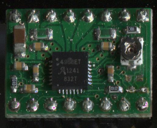
Here is my patched Pololu board:

(click for bigger version).

Thanks for sharing your modification!

- Ben