Hi,
I am attempting to use an OrangutanSVP 1284 with an A4983 stepper motor carrier to run a stepper motor from Lin Engineering (# 4218).
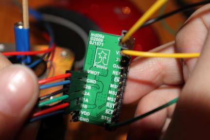
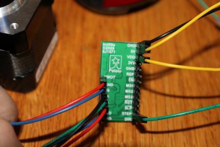
Based on the Pololu page for the A4983 and the Allegro datasheet, I’ve attached an ~17V power supply (well within the 8V-35V bounds) across VMOT and GND on the A4983. The 4 leads to the motor are connected to pins 1A, 1B, 2A, and 2B. (The attachments were made based on correlating the Pololu sketch of the two coils on a bipolar stepper motor and the Lin Engineering sketch). The logic supply voltage VDD was originally attached to voltage on the Orangutan; it is currently attached to the 5V pin on the A4983 because the documentation said that the logic voltage could be supplied through a jumper between VDD and either 5V or 3V3. The STEP pin is connected to a digital I/O pin (IO_C1) on the Orangutan.
Using a voltmeter and an oscilliscope, I’ve looked at the values of the EN, REF, RST, SLP, and DIR pin. They all appear to hold proper values by default so that the A4983 should allow the motor to run. (Individually, I’ve tried driving each pin both high and low through the Orangutan. I have not yet had a chance to try different combinations of the pins.)
One thought was that there is a current limiting potentiometer on the A4983–if it is in a position to allow very little current through, would that keep the motor from turning? Would that be the default position?
The code I’ve been using to drive the output pin on the Orangutan is:
  while(1)
  {
    OrangutanDigital::setOutput(IO_C1, HIGH);
	delay_ms(1);

	OrangutanDigital::setOutput(IO_C1, LOW);
	delay_ms(1);

  }
The osciliscope confirms that this code appears to be working.
Thanks so much for any assistance! I haven’t had much experience with this system or language before (I’ve taken Java in school and have programmed an FRC robot in Java. And while I have gotten the QTR sensors and some other sensors to work, this has definitely been problematic.)
Thank you,
Bianca Homberg