Hi,
I recently bought the a4983 driver and it works fine with a unipoler wired as a bipolar, and is microstepping correctly upto 1/16th.
my application is not robotics but simple motor control.
I basically want to use 1/8th stepping, so MS1-3 inputs will be set permanently, but with 4 different options using manual switches/digital latches for the following scenarios
Clockwise - Hi Speed
Clockwise - Lo Speed
CCW - Hi Speed
CCW - Lo Speed
Tracking - Intermediate
(Hi Speed for CW and CCW will use same clock freq, Lo Speed for both DIR will use same lower CLK freq)
I’m obtaining different clock frequencies using a Silicon oscillator - LTC6900, output to a 4060 freq divider.
To achieve one of the 4 states above, I thought of multiplexing one of the two different clock outputs from the 4060 (between 400 to 1200Hz) to the CLK input of the A4983, and using a ganged switch, set the DIR to CW or CCW.
I’ve thought of using either a multiplexer, or a non inverting buffer or a CD4066 bilateral CMOS switchfor a common CLK bus.
my problem is setting mux , buffer or cmos switch ctrl pin states using physical switches and pull down or pull up resistors, or digital latches (using a 4013).
A simple 2 input - 4 channel multiplexer should allow selection of any 3 frequency inputs from the divider with the following truth table
CTRLA CTRLB CHANNEL
L L 1
L H 2
H H 3
What would be the best way to set the above logic states using dpdt momentary switches
I don’t understand what you are asking for. Are you trying to get a latching circuit? Does your DPDT switch have a center off position, with three total positions, that you’re trying to convert into the three pairs of signals? Or can you use one switch per control line (in which case the answer is really simple - use each switch as a SPST switch from input to ground, and put a pull-up resistor on the input).
Hi,
I’m trying to achieve three functions for each switch.
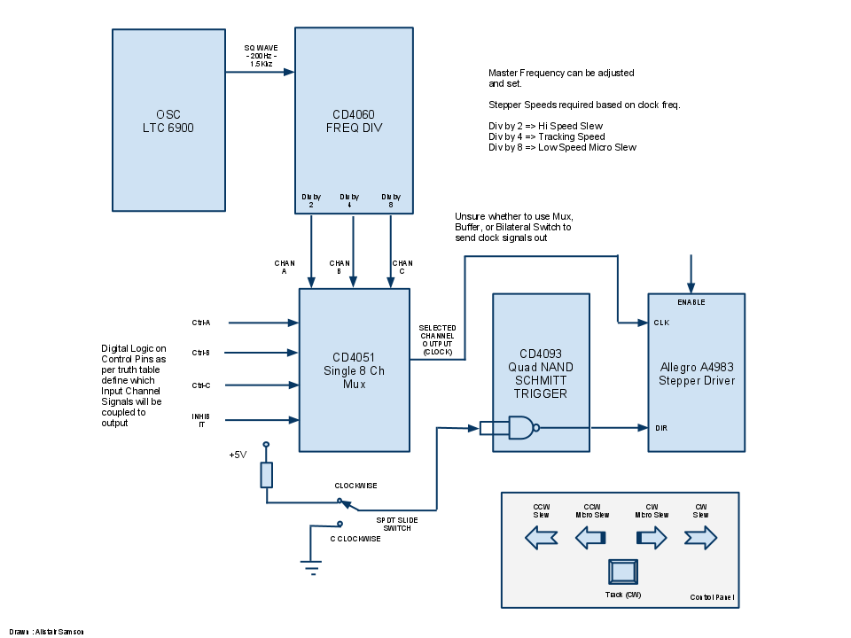
i’ve attached a diagram that should explain things a bit better.
The switches are
Clockwise-Hi Speed - Should couple hi clock freq to clock input of A4983+should pull ENABLE low+ should pull DIR low
Clockwise-Lo Speed - Should couple Lo clock freq to clock input of A4983+should pull ENABLE low+ should pull DIR low
CCW-Hi Speed - Hi Speed - Should engage hi clock freq to clock input of A4983+should pull ENABLE low+ should pull DIR high
CCW-Lo Speed - Should engage hi clock freq to clock input of A4983+should pull ENABLE low+ should pull DIR High
Tracking CW - Should engage mid clock freq to clock input of A4983+should pull ENABLE low+ should pull DIR low
I wanted to know what the best method for the above was,
to use a freq divider to get the 3 different frequencies, use buffers or multiplexers to couple any one of these to the CLK input of the A4983
engage one of three frequency determining resistors for the silicon oscillator LTC6900
But in both ways above, a single switch would need to enable the A4983 motor outputs with the EN pin, set DIR either low or high depending on which switch, and get the right clock signal to the driver.
I came across a one-shot latch using a 4013, so i think the 2nd method might work if I use a bilateral switch such as the 4066, and use the latch to couple one resistor in the clock circuit using the switch, pull enable low, and pull DIR low.
am working on the diagram and will post shortly.
Hi,
I just tested the second method of using switches to select different resistors in parallel to generate the 3 different frequencies, but it did not work properly. the waveforms were distorted, and the frequency was drifting all over.
but i also tested the first method using the 4051 multiplexer and a simple slide switch to select one of two channels, each of which are connected to two pins of the 4060 frequency divider, and it works well.
i just need a method of digitally incorporating the three functions using momentary spst or dpst switches.
i had to use one of the schmitt triggers to change the mux control pin states, as otherwise it was’nt reliable. i guess the same can be done with a pull down or pull up resistor.
Your post is still pretty unclear. You speak of five switches, but you also have that SPDT slide switch in the diagram (which, by the way, is not how you should use the switch: the pull-up should be on the NAND gate inputs, and you should leave that upper switch terminal disconnected). I’m also still not clear on if the switches are momentary and if you want some kind of latching feature.
By the way, I’m assuming you have to do this for some kind of digital logic class since this general approach would otherwise not be reasonable. You could just do everything in a $2 microcontroller and have way more flexibility in the details of how your system handles things like multiple switches being activated at once, adding acceleration and deceleration to the stepper control, and so on.
If you have to do this discrete logic approach because of external constraints (e.g. a “no microcontroller” rule), you should figure out what you want each possible combination of switch positions to do to your mux control inputs. If you have two selection inputs plus direction and inhibit, you’ll effectively have four five-input circuits that you can build straight out of your truth table. I assume your class covered techniques for simplifying the circuits, or if you do it in programmable logic, whatever software you have for that should take care of it.
Hi,
I only need five switches. the spdt slide switch in the diagram was when i did not incorporate dir control in the five switches.
Switches would be momentary except Mid speed which could either be a DPDT or a latch, and in the normally off state, they would need to disable the EN input, and enable INH for the Mux.
The reason for not using a microcontroller is only because I don’t have access to a programmer, am completely unfamiliar with programming and I thought it would be achievable with digital logic.
For my application the low speed selection should not have deceleration.
The truth table for the switches when depressed would be
X Y INH EN DIR
Lo Speed CW 0 1 0 0 0
Hi Speed CW 1 0 0 0 0
Mid Speed CW 1 1 0 0 0
Lo Speed CCW 0 1 0 0 1
Hi Speed CCW 1 0 0 0 1
Hi,
I did go through PIC and PICAXE microcontroller concepts, but I think i found an answer to what I’m looking for with a 20key encoder MM74C923N.
The outputs for my truth table are available by depressing the appropriate spst switch as below. It has built in debounce circuitry, and is tri state. only thing is i’m not sure what the mux output would be when its input is high Z (when keypad buttons are open), or the A4983 motor output when its EN pin is at high Z.
Keypad X Y EN INH DIR
12 0 0 1 1 0 - Need this o/p when switches are off to disable motor draw
1 1 0 0 0 0 - Hi Speed CW
18 0 1 0 0 1 - Lo Speed CW
17 1 0 0 0 1 - Hi Speed CCW
3 1 1 0 0 0 - Mid Speed CW
2 0 1 0 0 0 - Lo Speed CCW
You should really go with the MCU approach, especially if you want to be doing more of this sort of thing in the future. There are many relatively cheap programmers or boards that don’t require programmers, and the cost of doing it this discrete logic way is unlikely to be lower.
This encoder chip is interesting, and I guess it also takes care of a problem you had in your original truth table, which didn’t account for combinations of switch presses.
I had a look at the picaxe mcu which some forums suggested was the easiest to start with and it only needs a serial to stereo cable to program.
any suggestions on guides, i did go through the picaxe site and got some docs.
the PIC chip is more readily available, but looks like programming is in C or Assembly. is it harder to understand than the picaxe?
I presume my 3 frequencies can be generated by the MCU using its crystal freq as reference.
could you explain how this application would be done with an MCU? the acceleration part is interesting as steppers need to accelerate slowly, another good application would be position sensing by counting steps or using optical encoders, and PC interface for software control for the motors.
my application is for a fork telescope and astrophotography, the mid speed setting allows precise tracking matched at earth’s rotation for long exposures. so a pc interface would be handy.
would you recommend servo’s instead of steppers for this application as it has feedback and position sensing.
I don’t have any experience with the picaxe and no particular reason to recommend it. In general, we like Atmel’s AVRs more than PICs, and if you use something like the Baby Orangutan, you could even control a stepper motor directly (though you wouldn’t get the microstepping of the A4983). The details of the programming are beyond what’s practical to discuss now; you can look at the documentation to see if that’s something that seems approachable to you. Parallax’s BASIC Stamps are good starting point for beginners, and they have a lot of resources for getting started, so you might look around there first for some sample microcontroller applications. You could also get something like the BASIC Stamp Discovery Kit.
Hobby servos are easy to use if you have a servo controller, but you only get about 180 degrees of range, so that might not be enough for you.
Thanks. will check.
One last question, is it a good idea to add a buffer such as the SN74LS125AN for the CLK, if so, is it better to add it before the mux or after the mux?
Pls ignore my silly question. Just realized that the mux will have only 1 output. So the buffer would be after the freq divider.
I just got delivery of the encoder chip. hope to finish it by the weekend if there are no more issues. will post results.
Thanks to your remark on how this project can easily be achieved with mcu’s, i went ahead with the picaxes, and replaced all of my digital components with just one mcu that does everything and sends control signals to the stepper driver.
so i have just two components on my board, and with the picaxe’s basic language and 3 pin programmer, programming it is so easy.
my mind’s now opened to mcu’s and possibilities are endless. working on quadrature decoders for absolute positioning as well.
one thing i’ve been trying hard to crack is acceleration and deceleration for steppers. would you have any links that explains a practical concept?
Great! I’m happy to hear you went the MCU route and that it seems to be working for you. For the acceleration, there shouldn’t be that much to it. For your fast speed right now, you probably have some loop where you pause for some fixed time and then toggle the step pin and then repeat. To do the acceleration, you need to gradually change the step rate from your current rate to the new rate by changing the pause every time through the loop. If you’re using some hardware to generate the pulses, it might be more difficult to change the period on each step, but you could probably fairly easy go through at least a few preset speeds so that you’re not jumping from one speed straight to a very different speed.
Hi,
thats right, I’m using a toggle function to generate the pulses.
issue is that as the picaxe has a basic compiler, it is a lot slower and therefore the toggle function can produce pulses to around 400Hz at the most (mcu clock is at 16Mhz * 4).
it has another pwmout command that starts at 500Hz and can go over 20Khz, but problem with this is that i can’t decrement time to accelerate. so will have to find another way out.
but its good the way it is and hopefully should get my telescope slewing.
video of the mcu circuit with acceleration
i managed to ramp it up to 41Khz with load and without stalling at 1/16 microstepping.