A4983+Arduino...constantly needs sketch reloaded?

Hi guys. Ive searched high and low (no pun intended) for a soloution to this in my project. Its the one thing holding me back from making serious progress.

I have an arduino Mega 1280, and the pololu A4983 with current regulator, trying to keep a Nema motor phidgets.com/products.php?product_id=3313 running.

Everything is powered by this beastly supply

docs.google.com/viewer?a=v&q=cac … zndaBsdrnA

Overkill? Yes. Works? For the most part!

I followed the getting started with the A4983 thread, wired everything up without a micro controller, set my current to 1.2A. The stepper driver did heat up, so a beefy little heatsink and fan was added. For what i’m doing, a ton of torque is not required.

So heres the problem. After uploading the getting started code from this forum to the arduino, everything works…for about 2 minutes. Then the motor ceases to turn, but still hums. Ok. Most would suggest it’s a heat issue, but, doesnt matter if i wait 20 seconds or 20 minutes, upon reboot, the motor will still be just humming. Unplugging the arduino and reuploading the code fixes the problem, but again, for about 2 minutes. Sometimes less, its very sporatic. Other times it will appear everything is fine and dandy and run for longer than 2 minutes, but, eventually it fails. I should mention i’ve tried this with a much smaller stepper, with a very low current requirement, and i’m stuck with the same symptoms.

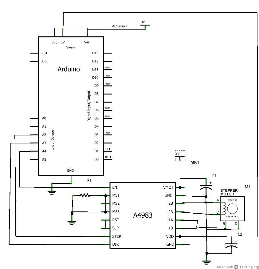
It was suggested on the Arduino forums that my problem may be the noise from the motor is interfering with the arduino, and causing the flash rom to partially start writting/resetting. Rather than trying to explain my setup, i’ve included a schematic from Fritzring. Ignore the connection between 5V and VIN…couldn’t get it to delete.

Now i’m on my second arduino board (fried the old one due to my own carelessness ) and the same problem persists. In order to try and test the theory on the arduino forums, instead of powering the A4983’s logic section from Arduino’s 5V, i found a KA8705 voltage regulator, and use that direct from the 9V supply to power the A4983’s logic. Again, same symptoms. Decoupling caps are used on the driver as noted in the attached schematic.

To further troubleshoot, i had the arduino code modified to illuminate a green LED on pin 12 while its stepping, then pause for 6 seconds and blink a yellow LED , then try to continue stepping. Once the motor stops working the LED’s continue to function as i programmed, so i’m a bit stumped.

Also trying to get it to change directions is noted as a simple task, but like everything else, doesn’t always seem to behave. Switching from high to low to change the direction will sometimes work, sometimes not. Like i said, usually works on a fresh code upload.

Anybody else experience issues like this? Its a really neat powerful board the A4983, i just can’t seem to chase this bug out of my system! Thanks in advance everyone.


What you’re describing sounds like it could be the result of bad ground wiring or possibly even a poor soldering joint. Are you sure you have a common ground between your Arduino and your A4983 carrier? Can you look closely at your header pins to make sure all the solder connections look good? Also, can you post your test sketch.

I suggest you make your system as simple as possible and systematically eliminate variables until you figure out what the root cause is. This means disconnecting the driver’s enable pin from the Arduino (it is internally pulled down) and removing your external voltage regulator (it should be fine powering the A4983 logic from your Arduino’s regulated 5 V). Also, to help keep overheating from causing added problems while you are debugging, I suggest you turn down the current to something a bit under 1 A (as long as your motor can still turn just fine with no load at the new current limit) and use a low stepping frequency (e.g. 50 or 100 Hz).

- Ben

Ben,

Alright, i’m sitting at my contraption now, trying the things suggested. The code i’m using from the pololu forums is:

#define stepPin 2
#define dirPin 3
#define enablePin 4
void setup()
{
// We set the enable pin to be an output
pinMode(enablePin, OUTPUT);
// then we set it HIGH so that the board is disabled until we
// get into a known state.
digitalWrite(enablePin, HIGH);
Serial.begin(9600);
Serial.println("Starting stepper exerciser.");
pinMode(stepPin, OUTPUT);
pinMode(dirPin, OUTPUT);
}
void loop()
{
int j;
// set the enablePin low so that we can now use our stepper driver.
digitalWrite(enablePin, LOW);
// wait a few microseconds for the enable to take effect
// (That isn't in the spec sheet I just added it for sanity.)
delayMicroseconds(2);
// we set the direction pin in an arbitrary direction.
digitalWrite(dirPin, HIGH);
for(j=0; j<=10000; j++) {
digitalWrite(stepPin, LOW);
delayMicroseconds(2);
digitalWrite(stepPin, HIGH);
delayMicroseconds(1000);
}}

I’m going to try this WITHOUT the enable pin as you suggested. Solder joints look ok, im using s giant desk magnifier to help me with my work. I agree with the grounding problem, as it seems the whine from the motor will change if i simply touch a flathead screwdriver to it in attempts to bias the current. Occasionally touching the heatsink gives a pitch change, so, yes, i agree there.

Just to better understand, how can a bad ground cause my code to go “corrupt?”

Also with the code listed above, shouldn’t it make more sense to call the Arduino’s stepper library? The part of the stepper library i never understood is the pin parameters. I know i need to use STEP and DIR, but the library can take more pins in a command. What would i use these for?

Ive included the breadboard layout im using. I couldnt figure out how to get Fritzring to list the power supply, but the right side of the board is the 9V supply, and the right side is the 5V from the arduino. Hopefully its not too rough to follow.

EDIT:

Alright. Ive tried the things suggested. Took it to bare minimum of just step and dir, powered A4983 from arduino, set current lower, even tried a smaller known good motor at 600mA. Removed heatsink, checked and resoldered all joints with a temperature controlled Weller. Same god darn results. Only this time, doesnt matter if i upload code or not. Motor spins until the arduinos sketch kicks in, then it just sits dead.

Im about ready to give up on this driver. I know many have had good luck, but it seems i’m not one of them. This whole project is for a senior design project that i’d like to have ready by the time i go back to school end of August, and i’ve spent nearly a month every night fighting with the same darn results. If i can get past this i can get into my control theory, LCD read out, second stepper, but yea, this is not working.

On a high note, my buddy scored me an ancient oscilloscope. 10MHz. 10$. Guy said it didn’t turn on. You’d think and older fellow would understand that tubes neat to warm up! Thing says it was made in 1972, yet still runs tubes. Manual with it is geared towards troubleshooting 50’s-70’s TVs (luckily for me 10Mhz is enough to trouble shoot guitar amps :smiley: ) Works with the iPod Touch acting as a function generator run right into it but unfortunately, i have no probe. On top of which, its the old bare wire/RCA probe style, can’t seem to come up with one on ebay. Anyway i can use this old gem in troubleshooting my problem? Or does it sound like i have a bum A4983

Im praying someone sees an error in my solderless board schematic. Thanks guys


Hello.

You wrote a lot here, and I’m not sure I was able to take it all in. I noticed a detail that looks wrong to me though. Your wiring sketch shows you connecting to the analog pins 2, 3, and 4, but I’m pretty sure your code is referring to the digital pins 2, 3, and 4 on the opposite side of the board. I don’t understand how you have it spinning at all if that is correct.

By the way, what is providing your 9V supply? How are you determining that your program is corrupted?

- Ryan

Sorry man, i can type faster than i can talk. Plus the replies of others on here is invaluable, so i try to get all possible factors out there.

Anyways. Dear god i think you are correct on the wrong pins. I can’t believe that mistake! I wish i was at my work area. Im checking the arduino reference and kicking myself.

I agree why the heck would i get any motion at all?

Reason on the uploaded sketch is, i placed LEDs on 12 and 13 (digital) to light up 12 as it steps in one direction, blink the 13 pin for a few seconds while it paused the stepper, then continue stepping with 12 back on. After awhile, this wouldnt even occur. 12 would come on and that was it. Reuploading would bring it back to life, and usually, got the motor going again.

But again, why it even worked at all, because according to the reference you are correct.

My 9v supply is the big 16A beast listed in my first post.

Thanks again! Ill retest and post results.

At this point I don’t have a good reason to believe that your code really is getting corrupted. If you have a bad ground connection, then the voltages on the pins can do all sorts of weird things, including changing over time as capacitors discharge and other conditions change.

The motor should not spin unless the step pin is receiving pulses, and the step pin should not be receiving pulses before the Arduino sketch “kicks in”. If the motor spins before your Arduino sketch actually starts running, then something very strange is going on (e.g. connection problems possibly related to floating driver inputs) and I think your diagnosis of corrupted code is probably not correct.

I suggest you try a few things:

  1. Ryan pointed out that your code is using different pins from your connection diagram, which could explain your problems. Make sure that the pins in your sketch are really the pins you are using!

  2. If you keep having weird behavior, put some pull-down resistors on the dir and step inputs and see if the behavior continues. If the stepper motor stops moving entirely, your signals to the motor driver are probably not what you think they are, and your inputs are likely floating or partially floating. If the weird behavior continues, try disconnecting the Arduino (but keep the pull-down resistors) and repeatedly tap the step pin with a wire connected to Vdd. If you can manually step your stepper motor, then it is unlikely the problem is with the stepper motor driver.

  3. Use an oscilloscope to look at the signals you are supplying to the board and make sure they really are what you think they are.

  4. Try different pins on your breadboard in case your breadboard is introducing connection problems. Also, note that a breadboard is generally not a good choice for high-current connections like driving a stepper motor, so you might try making direct connections to the stepper motor driver to see if that improves anything.

- Ben

Because you have essentially have a floating pin connected to the driver input, and the voltage on that pin can be inconsistently affected by what nearby pins on the Arduino are doing. The very act of programming the Arduino could induce voltages on your floating step pin that cause the motor to turn.

The code you posted doesn’t do anything with pins 12 and 13, and I don’t see any LEDs in your diagram. If you have done further tests that give more information about what is going on, you should give us more information about them. There could be other reasons why the LEDs aren’t doing what you think they should; I think it is extremely unlikely that your Arduino flash is getting corrupted, though it is possible that power disturbances/noise could be causing your Arduino to reset (it’s easy to add code to your sketch that makes unintentional resets obvious).

- Ben

I am infinitely happy to report, that Ryan was 100% correct. I moved the 3 wires to digital, and everything steps perfectly. No more motor whines, no more stalling, code executes perfectly. There is some brief steps at startup, but i’ll figure that out later.

Yes, i know my code does not include the LEDs, as suggested by you guys, I should go back to the basics. I added the code for the LEDs later, i just posted the simple sketch i was having issues with.

Well as i said, i feel like a n00b with this mistake, but i learned from it, and cleaned up my circuit in the process. Thanks again everyone! Now this project can move forward at full speed. :mrgreen:

I’m sorry you struggled with this for so long, but I’m glad the fix was ultimately so simple. Please let us know if you run in to any further problems or need help with anything (the sporadic steps at the beginning could probably be eliminated by putting a pull-down resistor on the step pin or by using an I/O line to control the reset pin).

- Ben

Ben,

Im glad it was a simple fix too man. I thought i’d have to order and wait again. But, like i said, i learned alot.

I do have one question about the a4983. Ive read never power up the arduino with the a4983 receiving power or you will blow your i/o pins due to current overload.

Is that the rule for 5V logic supply from the arduino? Or just general Step/DIR/MS1,2,3? I guess my question is, is it safe to not power up the whole thing and upload just to the board? or am i going to have have to add some resistors in attempt to prevent current overload?

I ask, because everytime i upload a sketch, i disconnect the arduino from the driver, hookup to usb, upload, then hookup my pins. Since I last posted I now have the arduino controlling enable, Step, Dir, step and step resoloutions, with sleep comming next… The a4983’s logic is now powered from my voltage regulator circuit, which is capable of delivering 1A. I know the a4983 doesn’t require this, but i plan on adding another one and some other 5V peripherals.

Thanks in advance.

Do you mean “never power up the Arduino while the A4983 is unpowered”? Where did you hear this? We don’t have specific experience doing something like this with the A4983, but connecting powered devices to unpowered parts is generally bad engineering practice and can damage things. Why not just power the driver’s logic from the Arduino’s regulated 5 V line, so that the driver and the Arduino always turn on at the same time?

- Ben

I read this on other forums. And yes i meant dont power the arduino while connected to the completely unpowered a4983. I cant remember which ones i read this on, this was ages ago. I figured it would be ok, i just wanna be safe. I didnt know if i’d blow something by not powering the the 8-35v supply while powering the logic, or not powering anything at all other than the arduino just to upload a sketch.

It should be ok to just power the driver logic with the motor power disconnected, but you should generally check datasheets to see if this kind of thing is ok for whatever particular part you are using. As I said in my previous post, I do not recommend connecting a powered Arduino to a completely unpowered driver (you should not have to disconnect driver power to upload a sketch).

- Ben