hi
Please excuse this post if this scenario has already been mentioned - I was not able to locate it.
I hooked up the Driver board to my 25v + 5v Power supply using the minimal wiring diagram supplied.
I don’t have the micro programmed yet. i was planning on using a wire to manually trigger the Step on the driver board to test. (and to set the Current Limiter)
The motor is a Wangtai Stepper Nema23 - 57BYGH218
when I switched on the power - the Stepper motor made a buzzing noise and the driver board became very hot very quickly.
I naturally powered down the circuit (approx up time was less than 5 seconds) - re-checked all connections etc all good
Now if I power up, the board gets hot again - but no motor noise / movement.
if the motor is disconnected - the Driver does not heat up.
Connections :
Vmot + GND ==> 24Vdc PSU with 100uF 50V cap
A1+A2 Red & blue phase of Stepper
B1+B2 Black & Green phase of Stepper
Fault - LED + 330e res to +5V dc
Ground (common 25v + 5v common ground)
/Enable , m0, m1, m2 = N/c
/Reset bridged to /sleep => 5vdc
step = n/c
dir = n/c
any ideas? (note: PSU is switching PSU 5V (no load measured @ 7v ) could this have fried the board?
no fault indication
Assuming that you are referring to the DRV8825, the logic supply voltage is 5.25 V maximum. Applying 7 V could have destroyed the chip.
It is almost always a bad idea to leave the inputs on ANY device unconnected, even for a short time, as stray electric fields can cause them to be triggered randomly. However, the data sheet claims that the inputs to the DRV8825 are protected by 100K pulldown resistors, so you should be OK in this particular instance.
There are two different versions of the DRV8825 carrier board. Which one are you using? There is a marking on the silkscreen side that either says md20a or md20b above the ground pad.
When the motor is connected and the driver is powered, the driver will deliver current to the stepper motor, so it is normal for it to get hot. If the heat goes away when the motor is disconnected, the driver is likely behaving normally.
Since you are using 24V to drive the motor, the current must actively be limited to prevent damage to the motor. Your first step should be to set the current limit to the rated current of your stepper motor. You can set the current limit without the motor connected by measuring the voltage on the “ref” pin. More information can be found in the “Current limiting” section on the product page.
I think you should start by simplifying your system by removing the resistor and LED from the FAULT, and you should try to find a cleaner signal source for your step input (such as a microcontroller I/O line). It is generally not a good idea to use a wire to manually trigger the STEP pin on the board, as each touch will typically produce a series of quick bounces that are too fast for the stepper motor to keep up with (three quick steps forward can turn into a single step backwards). Also, you should not leave the DIR pin floating as this could cause random direction changes and lead to unpredictable behavior.
As Jim mentioned, applying 7V to the board inputs could have damaged the chip. The DRV8825 datasheet lists the absolute maximum voltage rating for the digital pins as 7V, so it seems you are right at the threshold of what the IC can handle. The operating voltage range only goes up to 5.25V, so even if the IC is undamaged, those pins are not being used within spec.
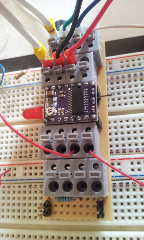
If you continue to have problems, could you post pictures and a diagram of your setup? Could you also post the code you are using to step the motor?
Hi Jeremy & Jim
thanks for your responses - All working well now
the culprit was as always a combination of things:
a) a nearly flat battery in my DVM !! providing me with the 7v reading
b) in my original test config, the Mode was set to 32 step - so my manual step pulses were actually working - i just didn’t see the movement !
Your suggestions to exercise the stepper via a clean digital signal was spot on. ( i can’t provide Arduino Code - Don’t have one, I used a PIC)