I’m trying to build a 6-axis device driven by 6 NEMA 14…17 stepper motors. I want to control this device from a Raspberry PI.
The bit I’m missing is everything between the motors and the raspberry and POLULU seems quite adept at providing solutions for multiple-axis stepper projects.
So, can anybody help me out by telling me what I need here?
I would think you need a beefy power supply to drive six steppers. Dunno if Pololu is right for that one.
Then you need six stepper drivers. Try the 8825: pololu.com/catalog/product/2133
Then you need some wiring from the RPi GPIO ports to the stepper drivers. Try the pre-crimped female-to-male wiring: pololu.com/catalog/product/2007
I think there are 12 available digital I/Os on the RPI GPIO. You need two for each stepper: step, and direction.
This is assuming that the stepper drivers accept 3.3V I/O, which it seems the 8825 does.
Then you need a bunch of mechanical assembly, screws, armatures for holding the motors and whatever they drive, axle shaft couplers, etc – all of that depends on what you actually want to do with your 6 steppers.
Hi, jwatte, and thank you for your intro! The 8825 is exactly what I was looking at when I decided to take a look and see if I got any replies yet but is this enough?
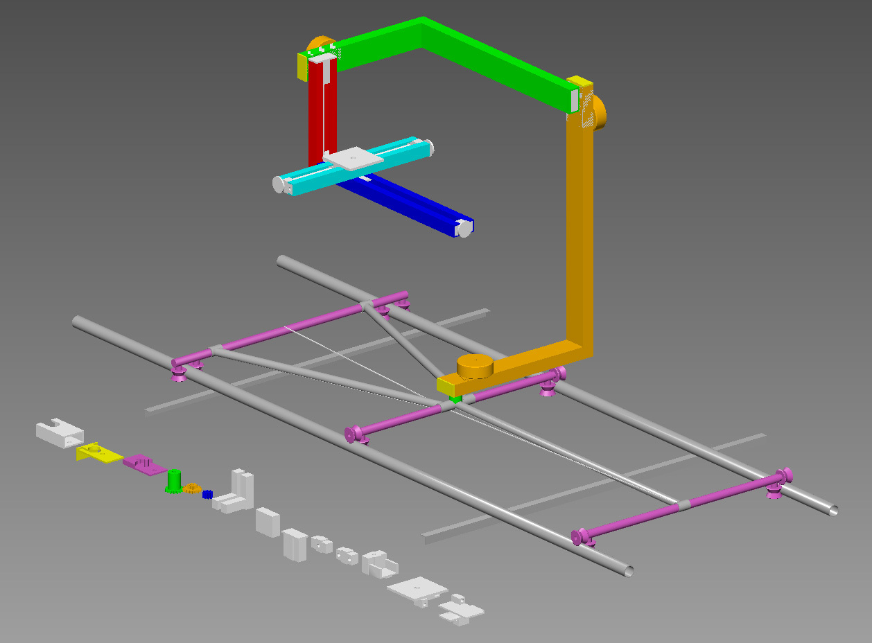
To answer your input: this project is a camera omni-head with 3 degrees of freedom, plus one more degree for traveling/dolly and two more degrees for controlling zoom and focus. This accounts for 4 NEMA 17 steppers capable of 4.8Kg-cm holding torque and 2 NEMA 14 steppers capable of almost 1Kg-cm holding torque. Yes, I know, some serious power gulping. This WILL require some external power, for sure. I get a sense that I’m going to have to power the motors with dedicated juice. I’m planning to make this “robot” portable and to power it from a solid 12V battery - with some power regulation.
So far, I found some Chinese drivers that are way too bulky - especially considering I need 6 of them. Plus, I am lately aware of all kinds of problems that can occur when the steppers approach the spec’ed holding torque or higher speeds - you can take a look here and see what I mean: http://www.youtube.com/watch?v=2SozZ7af3wg. What I’m looking for is a driver solution able to control and drive 6 steppers and which is compact enough - one that I could carry in my back-pack when hiking/trekking - and smart enough to operate in a way similar to what you saw in that video (able to avoid stalling, to run at high speeds, to “remember” where it needs to go etc.)
I am at the very beginning of the road in terms of robotics, so any pointers / guidance / help is very welcome!
The magic value you need to understand is the power draw of the motor, in amps. As long as that is matched to the driver, you should be OK – “running” current draw should be less than, say, 1/4 of the rated power of the driver, and ideally the stall current should be at or below the max set point of the driver.
You don’t need regulation to drive the motors, as long as your voltage is well within range of the driver’s ratings. The driver should be properly chopping the current so it’s limited to the set max limit. Higher voltage just means you get more starting torque.
Whether a controller is “enough” depends on what your computer can output. If the controller has step/direction inputs, you need some microcontroller to talk to the controller, and the computer talks to the microcontroller. An Arduino Uno would work fine for that. If the controller has serial input, you need a serial port on the computer, or a serial converter. One flavor of this is RS485 serial, which requires a specialized adapter – easiest is usually to build one yourself from an Arduino and a RS485 driver chip. If the controller has USB input, well, it should just work
That particular controller: It has USB input, so that would be “enough.” But look at this specification:
up to 1.1A coil current RMS (1.5A peak)
That’s less than the Pololu driver!
An Arduino Uno plus six Pololu drivers may be cheaper, and more modular to replace should you kill any particular part of it.
Yes, you should use a dedicated power supply for those motors. How many volts and amperes needed depends on your motors. If you use LiPo or LiFePO4 batteries, aim for 4S LiPi (14.4V nominal) or 5S LiFePO4 (16.0V nominal) but there should be significant room for variation. You want high-capacity batteries, which means you can draw more amps out of them; for LiPo you can also get “high C” batteries that allow higher draw as a multiple of capacity (“C rating”) although that won’t get you very long runtimes.
Hi again, jwatte, and thank you again for a comprehensive reply! I still have a couple of questions for you, if that’s OK
First, to describe a bit the working regime of my project: it’s a “time-lapse robot”. This means that I will be using it in 2 modes:
when setting it up, I might use the motors for longer periods of time (a couple of minutes) until I go through all the intermediary positions that I want to record as “key positions”
once set up, when running the program, the motors will run for a couple of milliseconds (while adjusting for a couple of degrees, not more) and then halt, for 5 to 60 seconds, before incrementing again to the next interpolated step.
Since we’re talking about time-lapse, it’s important to draw as much usage time from the battery as possible - I want to be able to time-lapse a whole day in the wild, for instance.
Now, the questions:
In the stationary times between 2 increments, when the system needs to stay put (and NOT vibrate or anything), how do I make the motors stay still (not allowing the weight of the levers to disrupt the current position)? The simple answer that comes to my mind is to keep the motors in place via the program, but keeping them under tension all the times will drain the battery much more rapidly, right? The more “exotic” answer would be to use some type of spring-loaded “brakes” on the reductions, brakes that normally grip the reduction in static mode and can be ordered to “release” by applying voltage to them, when the motors need to move. Any ideas/thoughts on that? Am I talking nonsense?
In the maximum load positions, the levers in the system (the weight of the camera etc.) will exert a torque force of around 4.5kg-cm, after the reduction is applied. It’s for this reason that I chose motors with at least 4.5Kg-cm of holding torque. How much holding torque would you say a motor should have spec’ed, if it is supposed to overcome these 4.5kg-cm? Again, I’m not interested in speed, just in force and micro-steps.
What is the most Amps-capable Polulu driver out there? And, based on that info, If I have to choose a stepper model, how many Amps should that stepper spec NOT exceed?
Since I clearly want to save money too, and since a modular design with separate drivers is always much safer, and since it’s also very light, I’d choose Polulu (84$ for 6 drivers) in a heartbeat, over the TMCM-6110 (340$ for a 6-axis pack). Even more so since it can provide more amps than the 6110. What holds me back about it is not knowing:
how to get to control the drivers via Raspberry PI? - do you have some advice on that?
if there’s a higher level language/interface to program it from Linux - some help here too?
how to wire everything up - I can’t find an exhaustive tutorial/help on that
if the Polulu drivers are at least as “smart” as the one in this video (stall-protection/detection? remembering where it had to go when interrupted or over-powered?): https://www.youtube.com/watch?v=2SozZ7af3wg - and no-one I ask seems to have an answer.
Well, it looks like jwatte is pretty busy these days. But I haven’t been sitting idle and I have apparently found the answer to my questions: Megatronics V2.0
I think I’ll go ahead and try it.
I personally would feel most comfortable running it this way, because of simpler code and more tutorials:
[I suspect you’re like me, not yet super pro at everything in this realm, but trying to tackle relatively big projects]
Have raspberry pi communicating via i2C to the baby orangutan. Raspberry Pi sends commands through some rudimentary communication protocol (invent it yourself! Or mimic the gCode used for reprap) for the baby orangutan to move the motors. You can even use the baby orangutan’s motors to drive brakes or something for your application.
Thank you for the suggestion. However, the baby orangutan breakout board only supports 2 motors, while I need to control six of them, plus 4 brakes. And I’m zero at designing electronics
This is where I am, right now, with the config:
A 12/24V high capacity portable power source (battery/mini-generator) with enough stamina to provide power for all the consumers specified below, for a minimum of 12 hours
6 stepper motors, rated 1A each, with voltages ranging from 6 to 10V and holding torques between 0.5Kg-cm and 7.2Kg-cm
4 passive (power-off) stepper brakes, rated at 24V/0.27A
4 micro-contacts for determining the reset/origin of the robot, and 4 high-speed switches, for controlling the brakes.
As of right now, my main concern are the Pololu drivers, which are ok but not very smart (no encoders or feedback). Here’s a thread I just started on reprap, about the idea of using smarter driver chips for Pololu-compatible breakout boards… http://forums.reprap.org/read.php?88,186139,186141#msg-186141 - hope it’ll yield something good…
pololu.com/catalog/category/12
Try this for your computer control it’s not just a servo controler and a one stop shop answer for nearly everything. You could even put 3drs wireless telementry transevers to it tx and rx lines. low power sleep mode just yum.
diy drone have the sdk programe and data sheets for the 3dr telementry.
Hi erosnicolau, the baby orangutan would be used in addition to six DRV8825 or A4988 black edition drivers. It would be the “real time” brains behind the commands sent from the raspberry pi.
It’s actually a suggestion similar to the megatronics board. I think megatronics is a perfect application of utilizing the reprap/3Dprinter developments. You can even run repetier-server to interface and remotely send the commands to the project.
As for drivers with positional feedback, just make sure you read the fine lines of what its capable of. Most that I’ve seen can only monitor rotations faster than 500steps/second, because there’s not enough back EMF (the stepper analogue of back emf, or whatever it is called) for anything lower than 500steps/second.
Traditional hall sensor encoding position sensors tend to be more accurate.
Mmm I looked for “baby orangutan” on Google and it showed me a small breakout board with 2 drivers on it… I must have found something wrong…
Anyway, I already ordered the Megatronics…
Wow, wasn’t aware of that… I had just discovered a driver that sounds amazing and comes in an affordable package (albeit double price as compared to the Pololu High Current one, but apparently worth it): the Trinamic TMC260, mounted on an Arduino shield and named TOS-100: http://www.motioncontrol-community.org/?page_id=353. You’re saying that I should double-check before cashing out double the money… and I will
One more question: aren’t hall sensor encoding position sensors limited by the graphic resolution of the film, and hence provide only a limited amount of finesse positioning?
There are linear optical sensors, which are limited to the resolution of their film. But, that can be very high, because they use high resolution x-ray film. There are even higher resolution capacitive sensing linear sensors, like digital vernier calipers (sorry I don’t know much about them besides that they exist.)
However, what I was suggesting is a typical grey-code rotational sensor like Pololu has on the back of their gearmotors+encoder. Those can be rather high resolution, depending on how you design it. At the least, you can use a rudimentary one it to see verify that your stepper is not skipping, and in turn, count your steps. The biggest problem with one of those in your application that I can imagine is that keeping track of the interrupts from 6 linear rotational encoders must be fairly processor intensive. Might not be suitable for a 20mhz arduino.
Hi, Tomek,
Can you give me a link to those encoders you’re talking about, so I can take a closer look?
I do have access to high-resolution x-ray film printing, so i CAN, in theory, print out pretty fine-print encoder scales…
About the numbers: Ideally only 2, possibly 3, at most 4, of the motors will need position feedback with encoders. Should we detect that the Arduino can’t handle the maximum of 4 at once, we can easily program them to run in pairs…
I am not sure what exact one we used at work (I am back at Uni now, this was from the last semester), but i think linear encoders like I was describing are quite common. For instance, a lot of scanners and printers use them, as do some of the hobbyist CNC people. What would suit your application the best, depends on your true requirements and application. For some reason, though, I think we used some quadrature encoders made from HP. Even if you have access to making your own film, I think it’ll be cheaper for you to buy the strips that go along with whatever system we use. After time and costs, and a loss in quality (it’s unlikely you’ll do it as well) I dont see any savings. Our workplace purchased the strips even though we used several hundred feet a year. It doesn’t make sense to produce your own unless you’re talking about much larger scales.
With the linear strips, you can have a dedicated quadrature decoder IC that counts the pulses and that way the arduino would have a much easier time dealing with the information. The linear strips have some benefit over rotational strips, but might require more structural support (again, depending on the specifics of your application.) So don’t forget to still investigate the regular rotational hall sensor systems.

 and POLULU seems quite adept at providing solutions for multiple-axis stepper projects.