Hello. I am making an interactive sculpture and to step down the voltage from my 13v battery power supply to 5v I was told by the guys at my Local Electronic Shop to use #2851 the 5V 5A Stepdown voltage regulator.
I am trying to drive a speaker, raspberry pi, a capacitive touch sensor, and a 60 NeoPixel ring with this setup. (I am also using a logic converter for the things that run on 3v logic, and a capacitor to smooth out the power curve.)
Unfortunately though the power is going from the battery into the stepdown regulator, it does not seem to be coming out. At my maker space we measured both power in and out with a multimeter. It showed 13v coming from the battery but only microvolts coming out. Suggestions?
Pictures on DropBox:
https://www.dropbox.com/s/uaqizskdc2ro0db/2015-08-09%2010.52.58.jpg?dl=0
https://www.dropbox.com/s/shykhk7dsa6zv91/2015-08-09%2010.53.12.jpg?dl=0
Hello.
I am sorry you are having trouble getting that regulator to work. Measuring a few microvolts for this scale of an application is basically like measuring electrical noise, so it might not be indicative of the actual voltage on the output. I recommend checking the continuity between the wires and the solder joints on your regulator to make sure you have good connections.
Can you also try removing all of the loads from the output of your regulator and measuring the output voltage again? Can you also post a picture that shows how you are measuring the output?
-Jon
Hello! Thanks for the reply, Jon. I will try to post pictures next week of the regulator power output without load and also how we are measuring the voltage.
Its been about a week; were you able to take any pictures?
-Jon
Hi there Jonathan! I moved recently, so sorry for the lengthy delay in getting you these photos.
Hi.
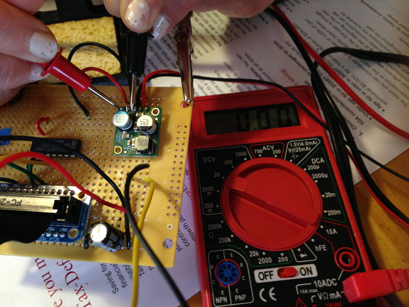
Can you verify that you can measure the voltage of your battery supply at the VIN and GND pins on the regulator? (For example, if your battery currently measures 13V, you should be able to put the leads of your multimeter on VIN and GND and also measure 13V.) I took another look at your DropBox photos from your original post, and realized I didn’t mention something explicitly in my initial reply: the two GND pins look like they might be cold joints or have insufficient (pad) wetting. Can you use your multimeter to verify continuity at those pins and the headers that attach to each of them? If they are not continuous, you can use the pictures at the top of this page from Adafruit’s Guide to Excellent Soldering as a guide to re-solder the joints.
-Jon
Hi Jonathan. Yes, I measured 12 V battery output at Vin and Gnd pins on the regulator, please see these other photos I will upload.
In your original post you mentioned that the system uses a 13V battery, but in your latest post you mention using a 12V battery. The picture in your latest post also shows that the input to the regulator is measuring 9.99V, which is a suspiciously low voltage for many battery chemistries that would nominally measure 12V. Can you tell me specifically what power supply you are connecting as an input to the regulator (e.g. 12V car battery, 10 NiMH AA batteries in series, 8 Alkaline AA batteries in series, etc.)?
Also, you have not commented on any of the soldering information I mentioned, and it looks like at least one of the GND pins is still bulbous and not wetted, so it seems like you have not tried re-soldering those joints. Can you use your multimeter to verify continuity at those pins and the headers that attach to each of them, and re-solder them if they are not continuous?
-Jon
Hi Jonathan. I will get the exact specs for the battery tomorrow; and try and resolder those pins you mentioned and see if that fixes the issue with the step-down regulator; thanks! Will let you know when I have results.
Hi Jonathan! Tonight I was able to test the continuity of all the pins and header as well as confirm the voltage coming into the system. I also resoldered the joints that you had pointed out appeared cold or unwetted and those are better now too.
To test continuity I used my multimeter, following instructions on LadyAda’s guide to testing continuity, but the continuity seemed to be fine.
I also got a better reading on the battery with the voltage coming IN of about 12.45 volts.
Unfortunately when I hook up the battery and test with my multimeter the voltage coming OUT of the stepdown regulator, there is still nothing showing on the multimeter (reading of 0). This shows when I use the pin as well as the wire connected to the header.
The battery I am using is the Zeus PC9-12SF2 (12V9AH) which is 12V.
Sorry no photos, as I could not hold the voltmeter and camera at once.
I am not entirely sure what the issue might have been, but it does sound like your regulator is not working. In general, devices like these can be sensitive to things like static shock, so you might double check that your work environment is not conducive to that kind of thing. Also, I am not sure if there are any hints on the other side of the board (where the regulator IC is) that might explain what happened. Regardless, if you send us an email with your order information and a reference to this post, I might be able to help you out with a discount towards a replacement.
-Jon
Thanks Jonathan. I have emailed the support email and included a reference to this forum thread! Hopefully everything will eventually work out well.
Thank you Jonathan for a pleasant customer service experience! 
When I get and have installed the new regulator and finish the sculpture project I will let everyone know here.
Hello! I tested the new 5v 5a stepdown regulator’s output and it works great!

