Hello Pololu People,
Wondering if someone here may have experience with the 50:1 Metal Gearmotor 37Dx70L mm 12V with 64 CPR Encoder (Helical Pinion) - Pololu item #: 4753 ? The motor is coupled with the Dual TB9051FTG Motor Driver Shield for Arduino - Pololu item #: 2520. Everything functions well at RPMs higher than 15 RPM. At RPMs lower than 15 RPM, the encoder sometimes erratically returns zero values to the pulsIn function - pulseIn (encoderPin, HIGH, 10000). Moreover, I observe with an oscilloscope probing directly at the encoder pin that the pulse width fluctuates drastically at low RPM - please see pulse width/RPM comparisons listed below:
Perhaps there is a minimum operating RPM for the encoder?
2900-4100 us pulse width : 1 RPM
2400-2500 us pulse width : 15 RPM
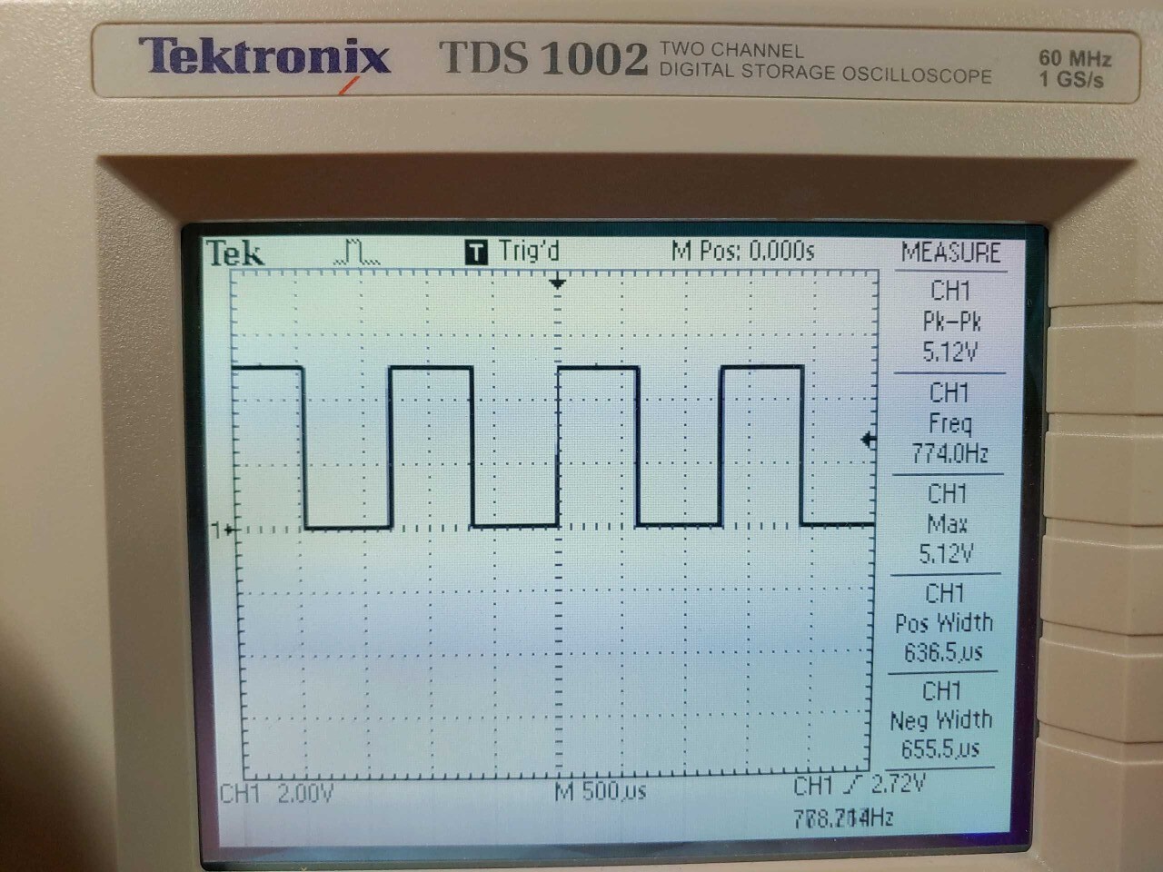
610-650 us pulse width : 60 RPM
Cheers,
Sean
Hello.
It might be possible that you are just seeing the motor speed fluctuating more at lower duty cycles, which would not necessarily be unusual. How are you driving the motor and measuring its speed when you look at the pulse width measurement? Also, could you post your scope captures of the encoder channels?
Are you only using one encoder channel? The pulseIn() function is blocking so it is generally not a great solution for reading encoder counts. You might instead try using one of these rotary encoder libraries that supports interrupts.
Brandon
1 Like
Hello Brandon,
The motor is driven by PWM with the TB9051FTG Motor Driver Shield for Arduino provided by m1pwmPin, and using only the Encoder-A channel.
The time period between two Encoder-A high pulses is determined using the pulseIn() function [totalpulseTime = pulseIn (encoderPin, HIGH, 10000)], which is then used to calculate the actual motor RPM as follows:
encoderTime = (totalpulseTime) * 32 (32 total high and low pulses/rev.)
encoderRPM = (1000000/encoderTime) * 60 (1000000 us)
actualRPM = encoderRPM/50 (50:1 ratio)
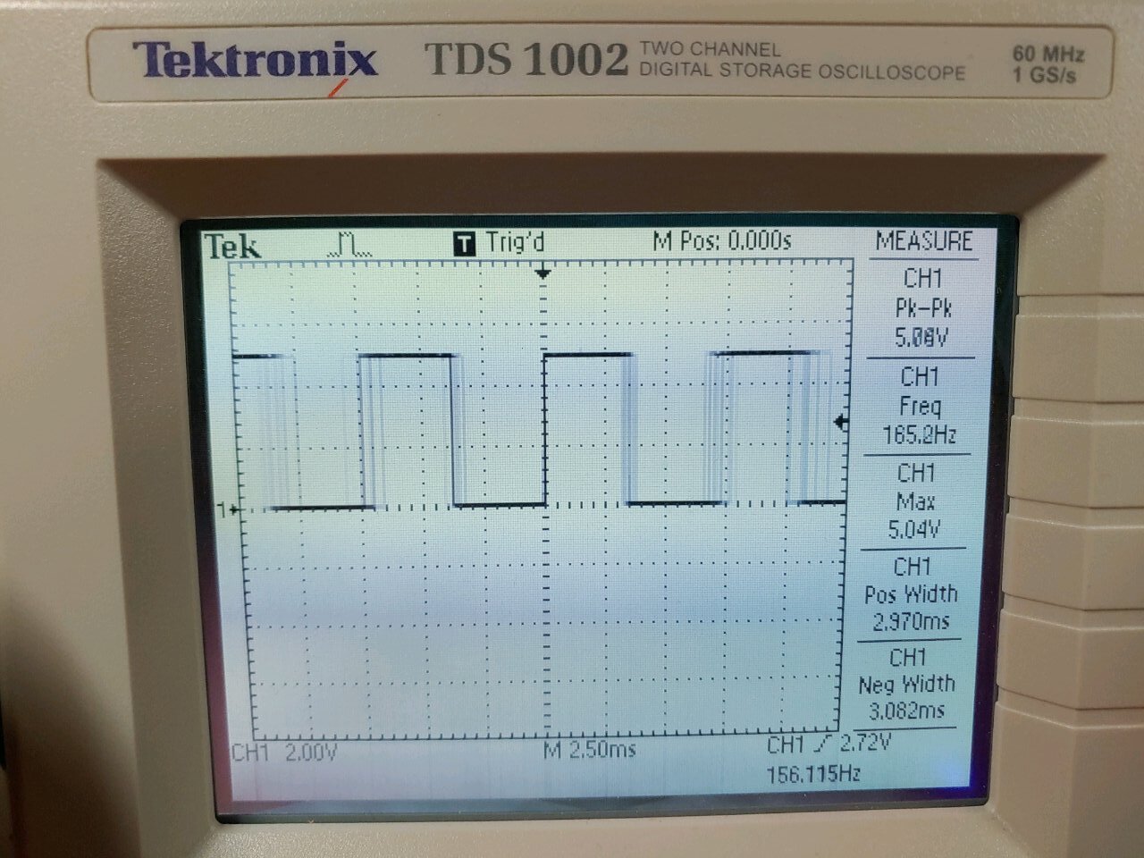
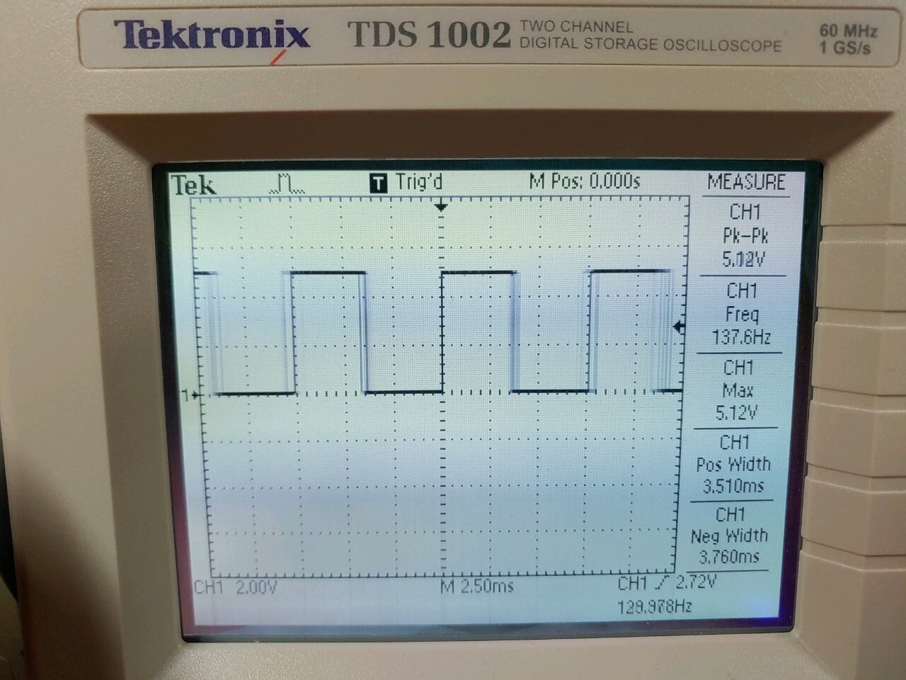
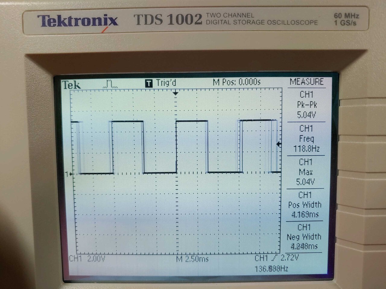
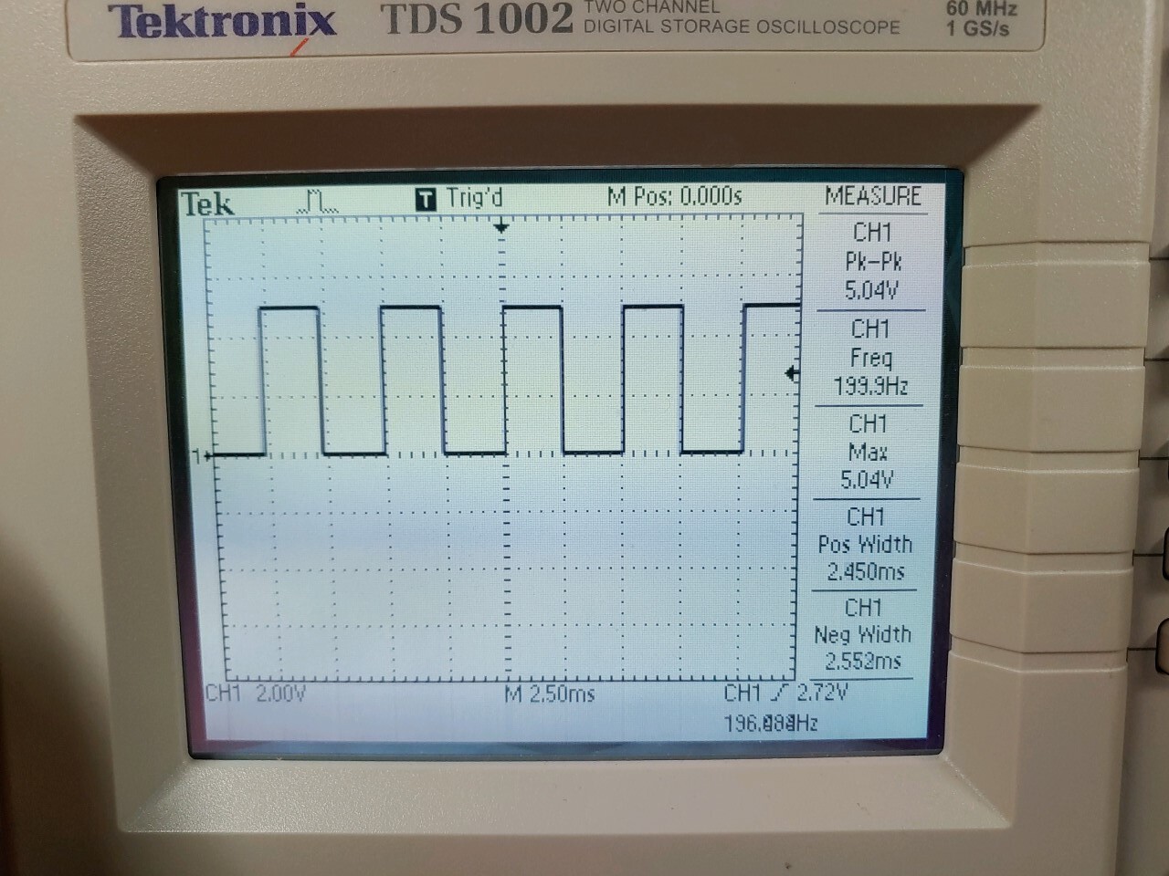
Please see the scope screen captures for 1, 15, and 60 RPM.
You may observe that the low 1RPM (3 photos) shows highly fluctuating values and blurred scope pulses; the 15 and 60 RPM were stable with minimal fluctuation, and no blurred scope pulses.
I’m am curious what “blocking” means regarding the pulseIn() function?
Sean
I suspect what you are seeing could be a combination of the magnetic disk not being completely symmetric and the cogging effect of the motor and its magnets being more apparent at low speeds. It looks like your first few scope captures show about 10 RPM (instead of 1 RPM); for that motor, that’s only around a 5% duty cycle, which might be getting close to the minimum required to overcome the cogging torque.
In general, I would recommend taking multiple samples of the encoder pulses and averaging them to help account for any variations caused by those kinds of factors. Since you are measuring the high portion of only one encoder signal, there will be 16 pulses per revolution of the magnet, so for best results I suggest taking a number of samples equal to a multiple of 16.
When code is “blocking” it means the program has to wait for that piece of code to finish before continuing. So, while your code is measuring the pulse with pulseIn(), it cannot do anything else. Similarly, if you try to have your code do something between measuring pulses, it might not start timing the next pulse as soon as it goes high, which could cause extra error. Using an interrupt helps solve that timing problem. You can find more information about interrupts on Arduino’s reference page.
Brandon
1 Like
Thank you for your highly professional reply, Brandon.
Glad to know that I’m on track with the encoder, the documentation provided by you guys at Pololu is excellent. This is only my second time playing with a motor, and with a little coding, the motor RPM is smoothly maintained under varying loads. The interrupt tip is appreciated; I imagine with interrupt vectors, one may be able to average all 64 pulses from both encoders with no blocking concerns.
Now I’m looking into current sensing to maintain maximum motor current using the ACS711EX.
Sean