After some searching I couldn’t find anyone that had attached the new mico gear motor encoders to the 3pi platform. At the black friday sale I picked up a little bit of everything and spent an hour putting it together this morning. It is an intermediate soldering job to do the following. The good news is that everything fits.
Remove the stock 30x1 3pi motors. (Unscrew the plastic motor cover, and then desolder the two motor pins from the 0.1 inch pins.
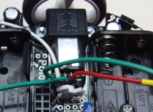
Solder at least 4 wires to the module. I used wires terminated in standard 0.1 inch pins, but you can also use 2mm cable as the pin spacing is 2mm instead of 2.54 mm. This is a bit fiddly after two cups of coffee. (Hey pololu, dump the M1 and M2 and give us a 2.54 connector for fat american hands. ( I really wanted to solder a 2.54 mm male header here. Yes I have 2mm headers from working on so many korean projects, but who else does!)
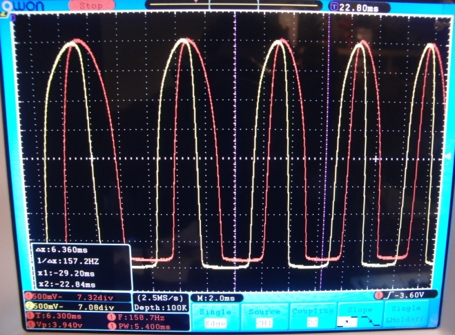
Hook up power and ground and check the output on a scope.
It is going to be a bit tricky as it would be nice to have one interrupt per encoder, but I will steal IO off the LCD to make this work, the other interrupt is tied to one of the motor control pins. I will probably end up using the pin change interrupts.
Awesome project! I added encoders to my 3pi, too, but I did it slightly different. I replaced the motor brackets with the extended micro metal gearmotor brackets, so I could keep the female headers for the 3pi expansion kit. I plan on reading the encoder outputs with a microcontroller on the expansion kit and have the serial slave program loaded on the 3pi.
By the way, it looks like you put the encoders on the shaft backwards. You will get better results if the teeth are closer to the sensors (from your oscilloscope capture, it looks like you may have already flipped them correctly).
I like how those brackets let you move the motors more outboard and make it slightly less cramped. I experimented with putting the encoder wheels on in both directions and got better results this way according to the signals on the scope.
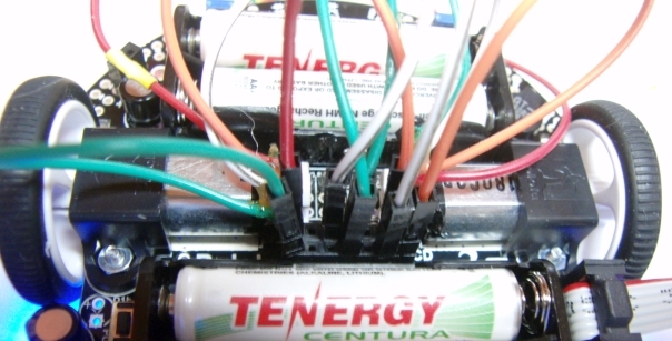
I have used the LCD pins as input pins for the encoders.
Green → Ground 2x for the encoders 1x for the USB to TTL interface
Orange → encoder 1 on each motor
White → encoder 2 on each motor
It took a bit of experimentation to figure out which pins would work with the different interrupt vectors but using pins (9 and 13) along with (4 and 12) seems to work, and these are all free with the LCD removed.
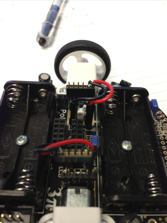
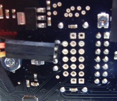
With the LCD removed, you will need some way to monitor the board. The easiest way is to hook up a serial monitor to pins0 and 1. These are conveniently available and can be brought out the bottom of the board. Attach these to any TTL to USB converter (CP2102 or FTDI) and you can use the serial monitor. See the image below, note you also need to tie the ground on you USB to TTL module to the ground on the board.
Here is a quick implementation using the Pololu Wheel encoder library ported from AVR c to the Arduino Environment. NOTE you will need to have a serial monitor hooked up to make this work.
#include <PololuWheelEncoders.h>

PololuWheelEncoders encoders;  //instantiate an encoder object

int i = 0;
int temp1 = 0;
int temp2 = 0;

void setup()
{
  Serial.begin(57600);
  delay(200);
  // Initialize the encoders and specify the four input pins.
  encoders.init(9,13,12,4);
}

void loop()
{
  // Read the counts for motor 1
  temp1 = encoders.getCountsM1();
  Serial.print(i);
  Serial.print(",");
  Serial.print(temp1);
  delay (100);
  // Read the counts for motor 2
  temp2 = encoders.getCountsM2();
  Serial.print(",");
  Serial.println(temp2);
  delay (100);
  i++;
}
Next is to wrap up some primitives for motor control. Maybe make a nicer cable.