I have a 36v8 (#3731) connected to a 5A motor. I am using the high power Arduino library with an Arduino Every and getting a step pulse train up to about 150us per step using half stepping. I saw a comment in the example code about instability for delays under 2000us. Is there any more information on why this is? Are the MOSFETs unable to switch that fast as the DRV8711 claims to support up to 250KHz?
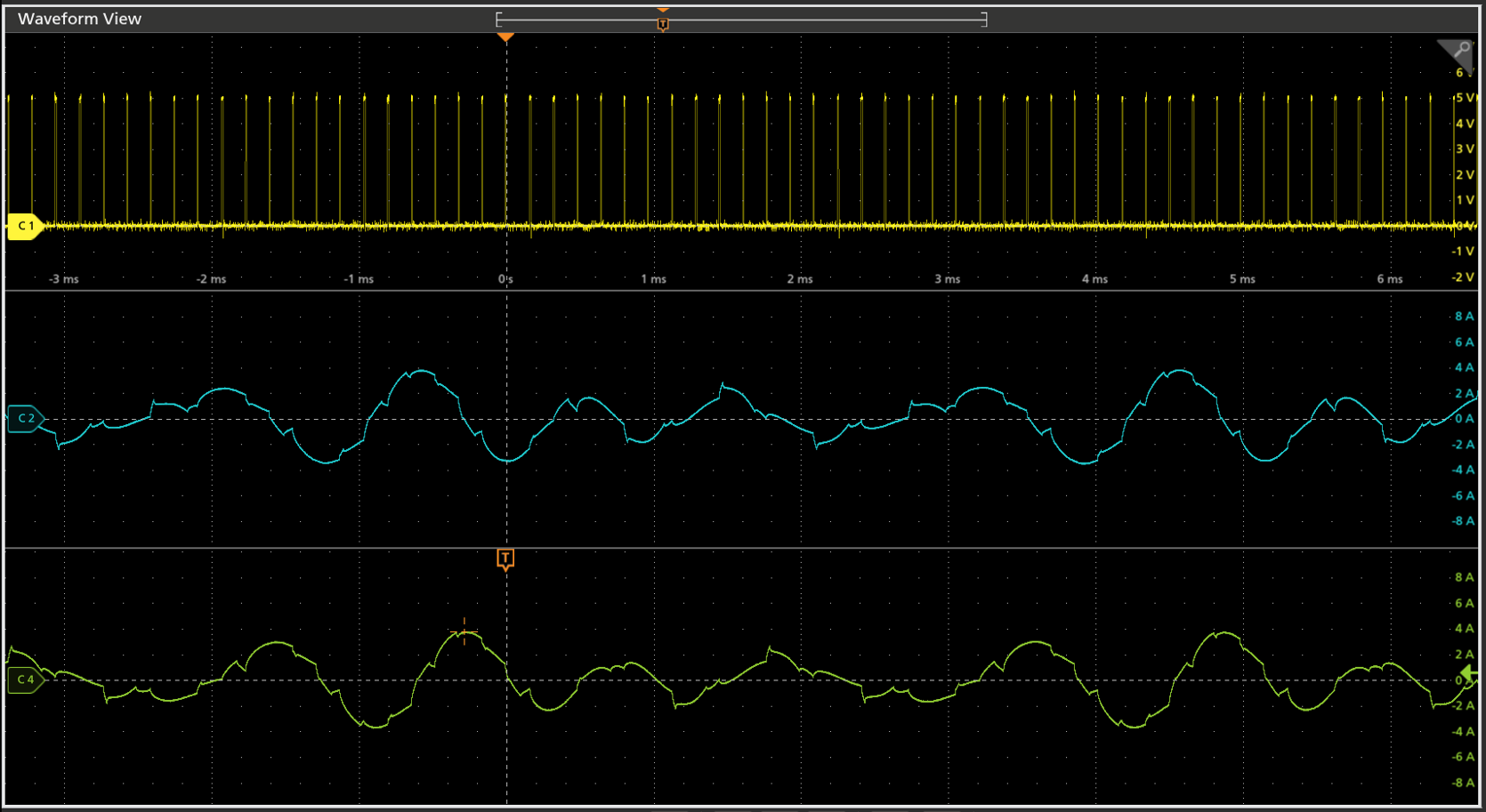
In my configuration, I am pretty sure the 36v4 is effectively skipping steps when run at my current speed, ~6.6Khz per step, and the current waveform on the two phases is very rounded over and not stable between the phase cycles. Any thoughts on why this would be? The pulse train itself is a bit slow but looks like I would expect otherwise.
It sounds like you are referring to this part of the code:
// This period is the length of the delay between steps, which controls the
// stepper motor's speed.  You can increase the delay to make the stepper motor
// go slower.  If you decrease the delay, the stepper motor will go faster, but
// there is a limit to how fast it can go before it starts missing steps.
const uint16_t StepPeriodUs = 2000;
Please note that this comment is not referring to a maximum step rate that the board or driver can handle; it is just generally stating that there is a practical limit to how fast you can actually step the motor. This limit is typically imposed by the motor and not the controller.
Could you post more details about the stepper motor and power supply you’re using? A link to spec sheets or product pages would probably be most helpful.
Also, you could try adjusting the decay mode to see if that helps smooth out the waveform.
We are using a NEMA 23 200step motor with a 5A max current (1.27mH and 0.39Ω per phase). A 5:1 gearbox is mounted on the front of the stepper.
The power supply is a BK9205 set for 28V and set for a 7.2A input current limit which should be plenty. I originally had this at 5.2A and saw no difference when I increase the limit.
With this motor inductance and its voltage I would expect about 227us to transition between 0 and 5A but with half stepping we are never quite that high.
In the software I call “sd.setCurrentMilliamps36v8(5000);” to set the maximum current for the DRV8711 and “sd.setStepMode(HPSDStepMode::MicroStep2);” to use half stepping. All other settings are the default from the example BasicStepping.ino in Github.
One other observation, when the drive is stepping at 100 steps per second I see a clean 1/2 step pattern like I expect and a slew rate that might be contributing to the current profile rounding. For a drop from +4A to 0A, the slew takes about 200us but is not linear like inductor charging and is more curved such as perhaps a gate charge? This seems consistent for positive current changes. For negative current changes its basically double. A -3A to 0A transition is virtually 400us. It seems like with these slew rates there is no way to support a 150us step period that we are targeting.
Do you have any other thoughts? I will play with the decay mode to see if that does make any significant improvements.
It sounds like you’re trying to target around 1000 RPM. Could you post a link to the datasheet for your stepper motor? Have you checked for a pull-out torque curve to get some idea of what kind of speed you can expect from your motor under the load of your system?
I suspect trying different decay modes will give you different results. You can find more information about the different decay modes and optimizing them in the “DRV8711 Decay Mode Setting Optimization” application note, which can be found under the “Resource” tab of the driver’s product page. Additionally, you could try using a higher operating voltage (e.g. 36V) since that show allow the current to ramp up faster.
Is any information available on the FETs for this board? I want to take a brief look at the Qg to understand the enable time for the FET when it is switching.
All the back calcs for the FETs look good. It appears that the motor is effectively 4mH so at 28V input we can only push 7mA/uS or maybe an amp for 150us/step. It’s just a voltage game or a different motor at this point.