I am using the 36v4 stepper motor driver to drive a stepper motor.
The motor makes knocking noises while it is running. It doesn’t make it constantly, but every 2-5 seconds it makes a faint grinding or knocking noise. Sometimes, it gets worse, one knock every 0.1s.
What could the problem be? I am using the BasicSteppingSPI program, and have set the current value to 1000 mA. I tried to vary the MicroStepping factor from 1 to 32. The issue I was facing is that this driver is for driving bipolar motors, and I have a unipolar motor. For this reason, I had to cut down the current running in the whole phase in half (more than half, for safety measure).
The power supply is an 230 V - 24 V, 4A toroid transformer, with 25.9 V RMS on the secondary. Connected to it, I have a full bridge rectifier and a big filter capacitor (10000 uF). The output voltage is 36.6V, which is expected (Uout*sqrt(2)).
All of the pins going from the board to the Arduino are properly soldered and have good connection
5V - IOREF, !SLP
GND - GND
D2 - DIR
D3 - STEP
D4 - SCS
D11 - SDATI
D12 - SDAT0
D13 - SCLK
I use the !SLP pin to deactivate the driver when I make changes to the code.
Are you able to shed some light on this issue?
Can a stepper motor make noise if it’s underpowered?
Is the power supply not stable enough?
If that does not fix the problem, can you post a video of the problem? Do you have any load on the motor? You might try monitoring the input voltage if you are not confident in your power supply. Do you have a different power source you could try?
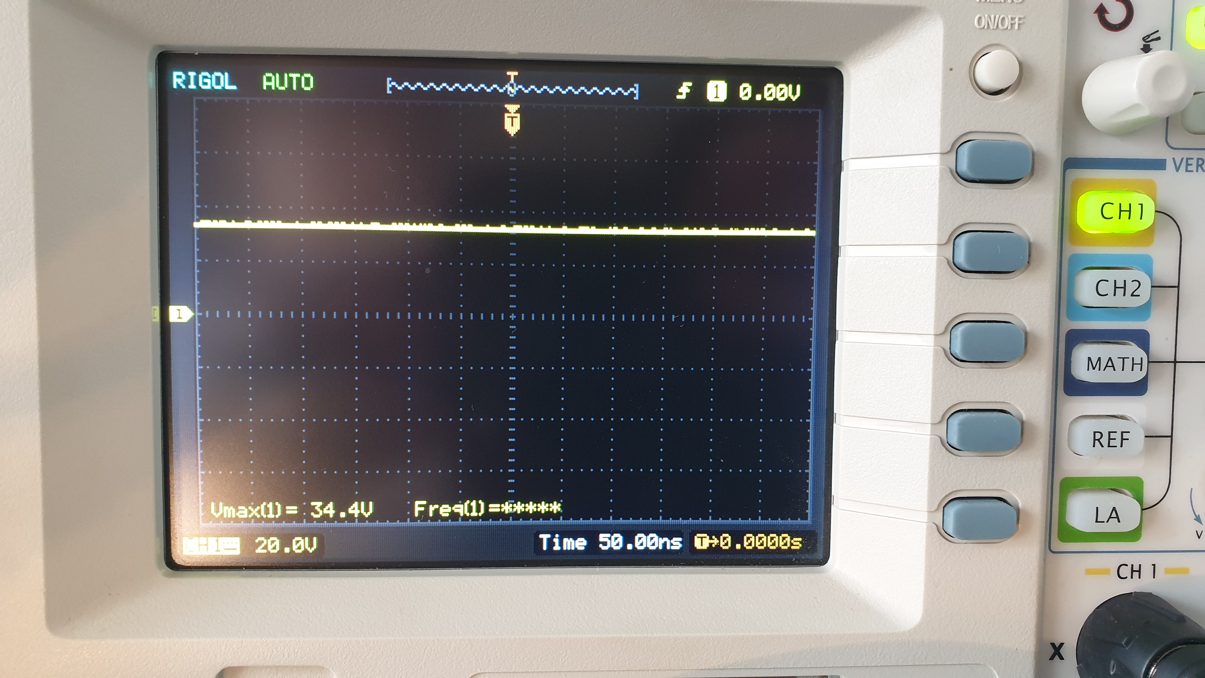
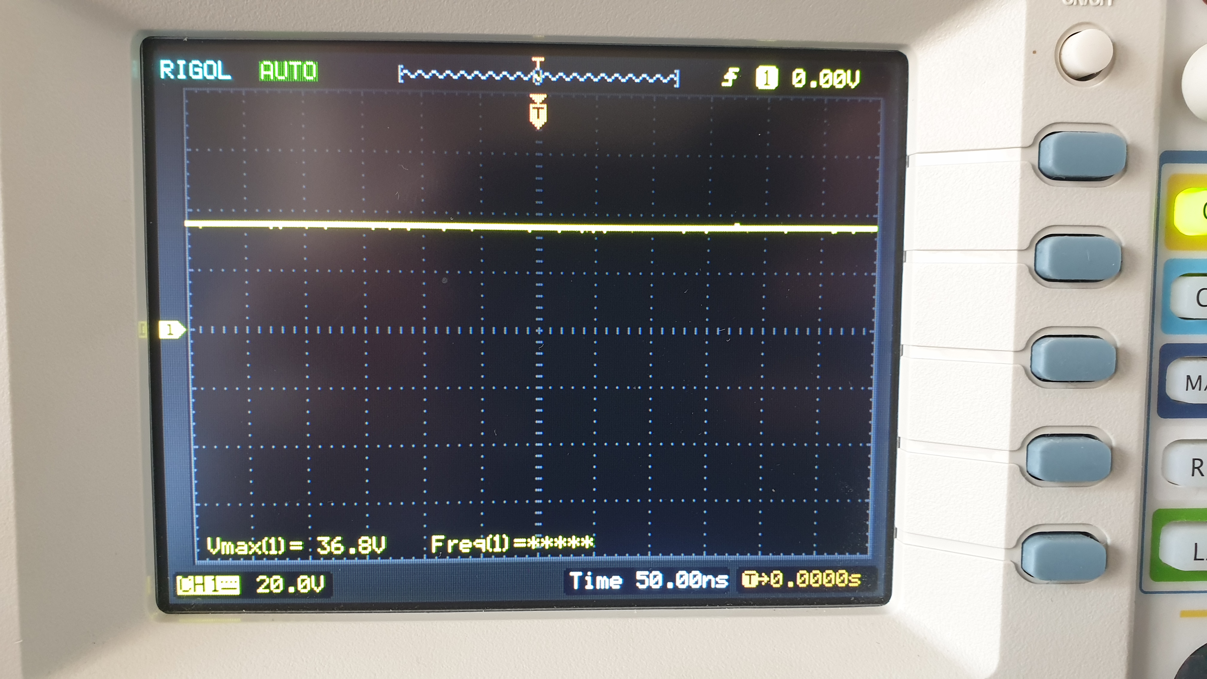
I started by testing the power supply.
No load voltage is 36.8V, shown on the 2. picture.
10W load on it lowered the output voltage to roughly 34V.
The output is still flat, shown on the 1. picture.
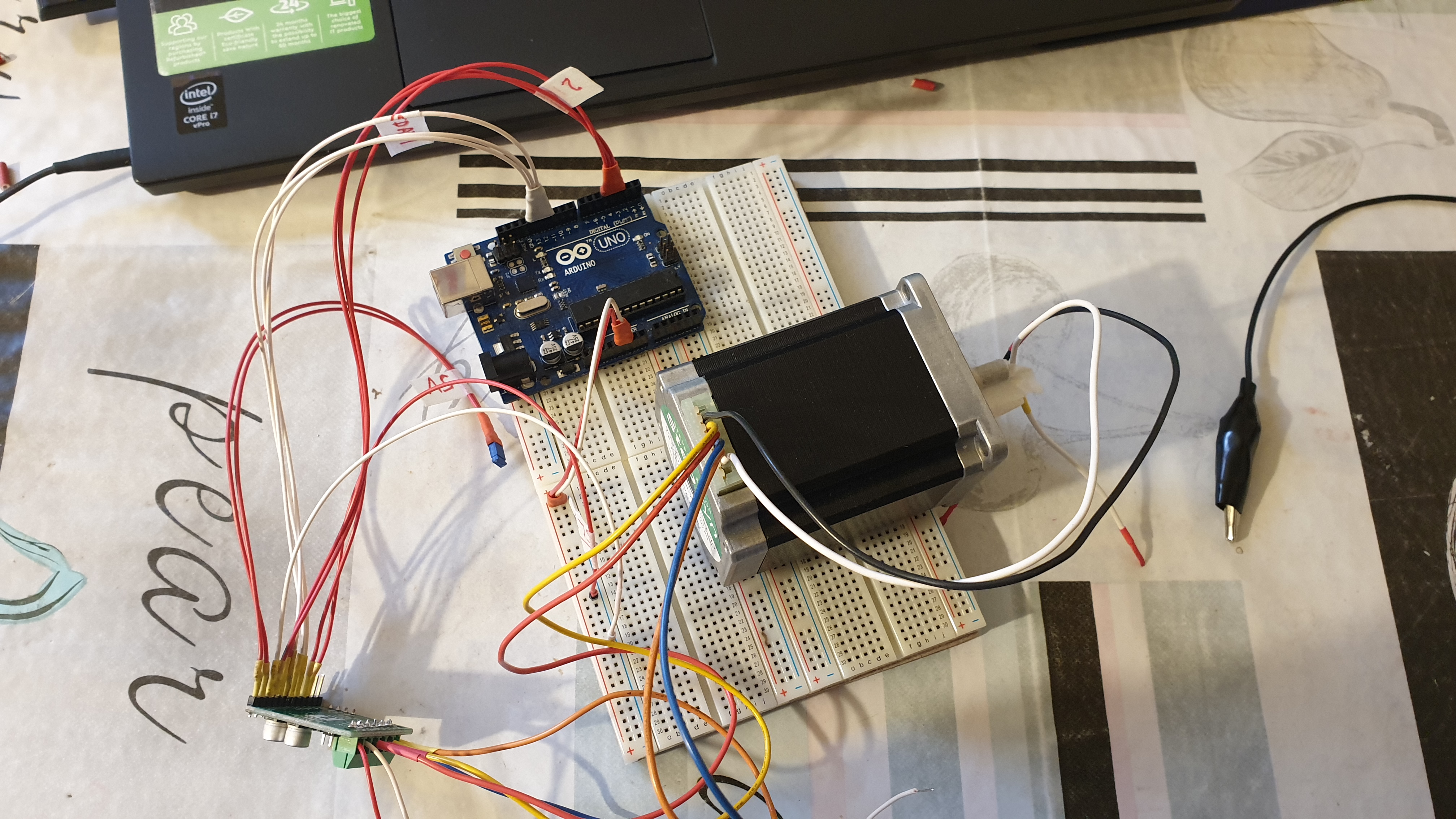
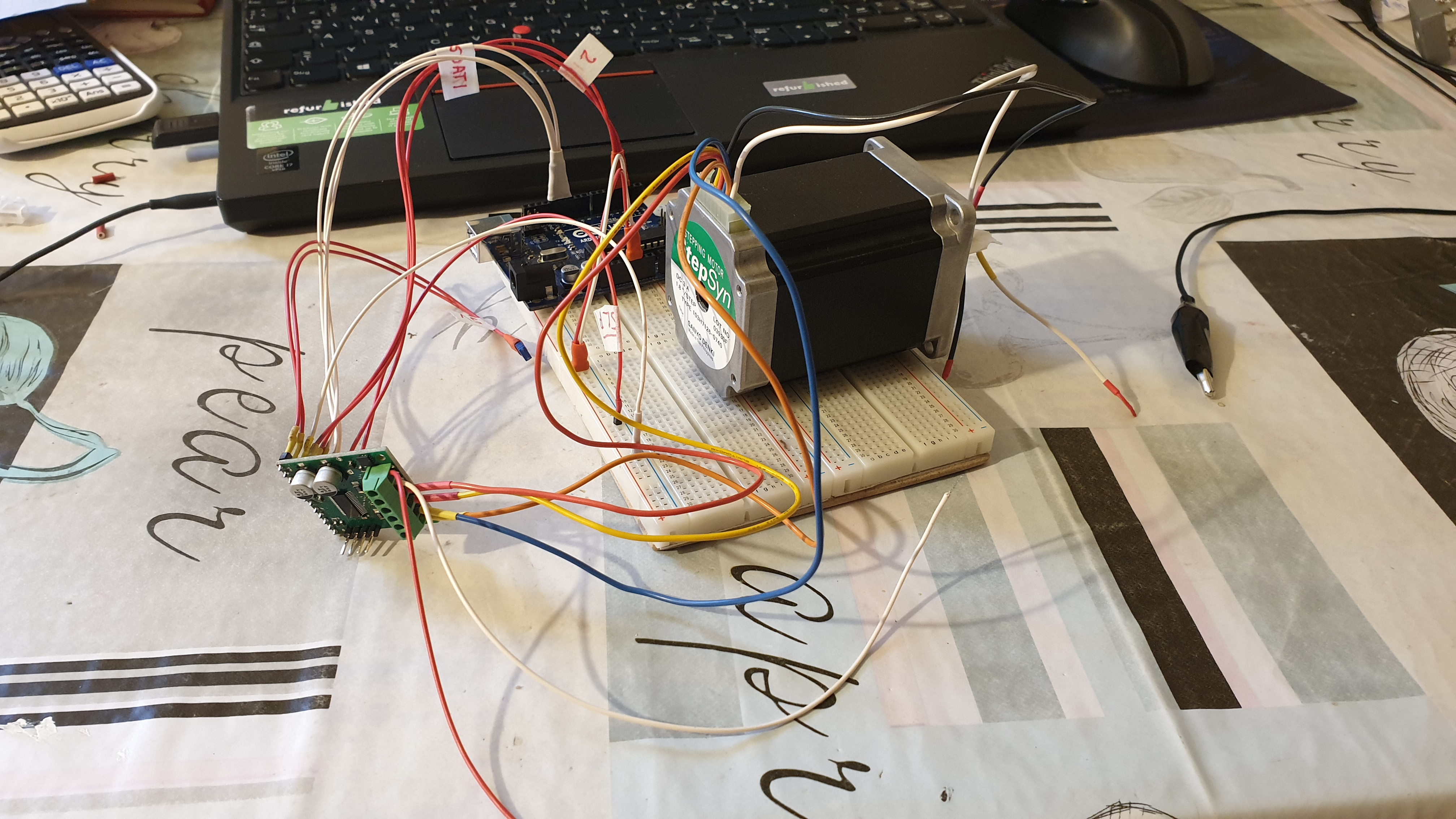
These are some pictures of the general arrangement.
Subsequently, I tested the input voltage on the driver while the motor was running the standard, non altered BasicSteppingSPI code.
Only thing that I had altered in the code is the current limit, I had lowered it do 500mA, because then it wouldn’t make the strange noise.
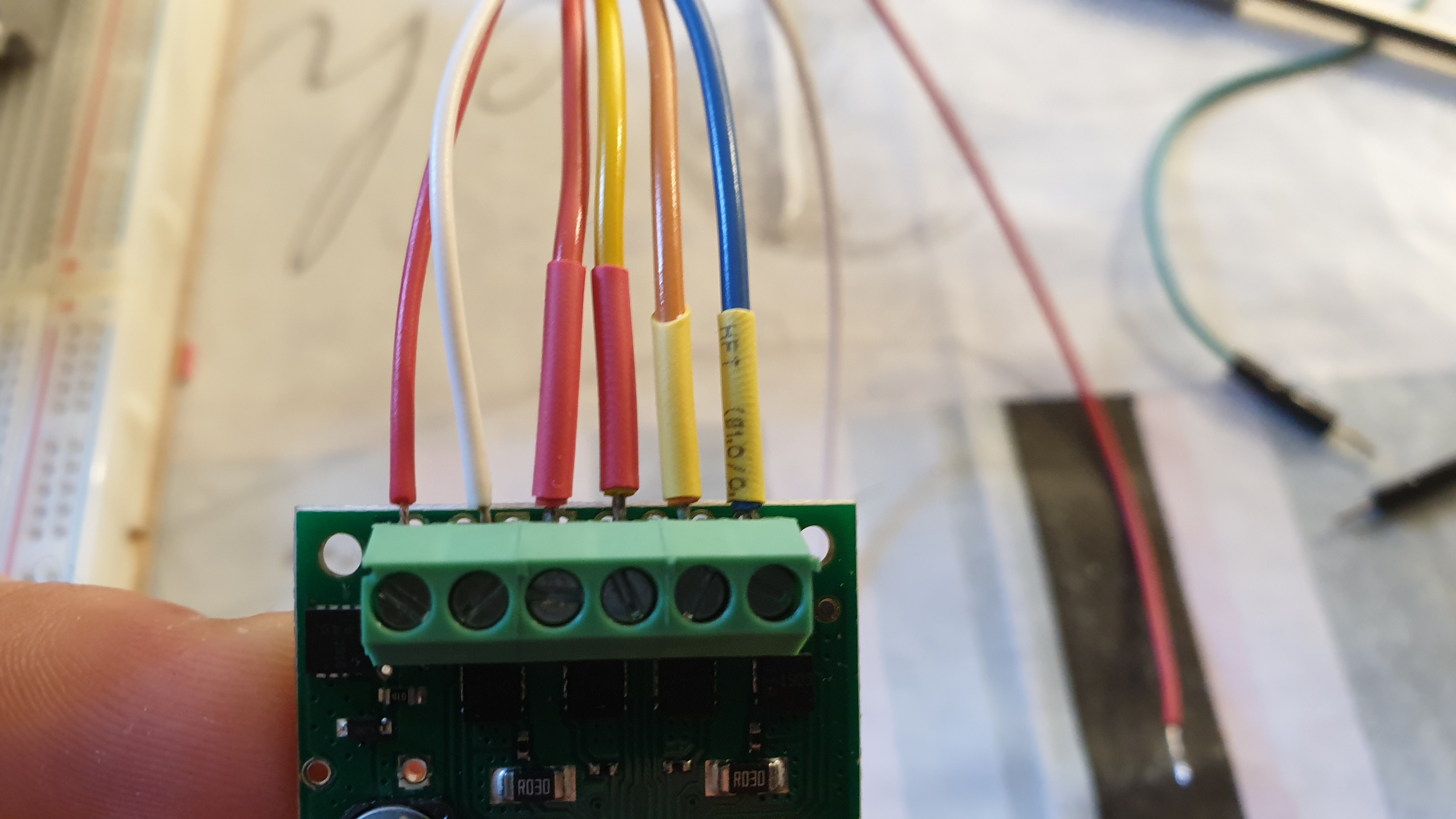
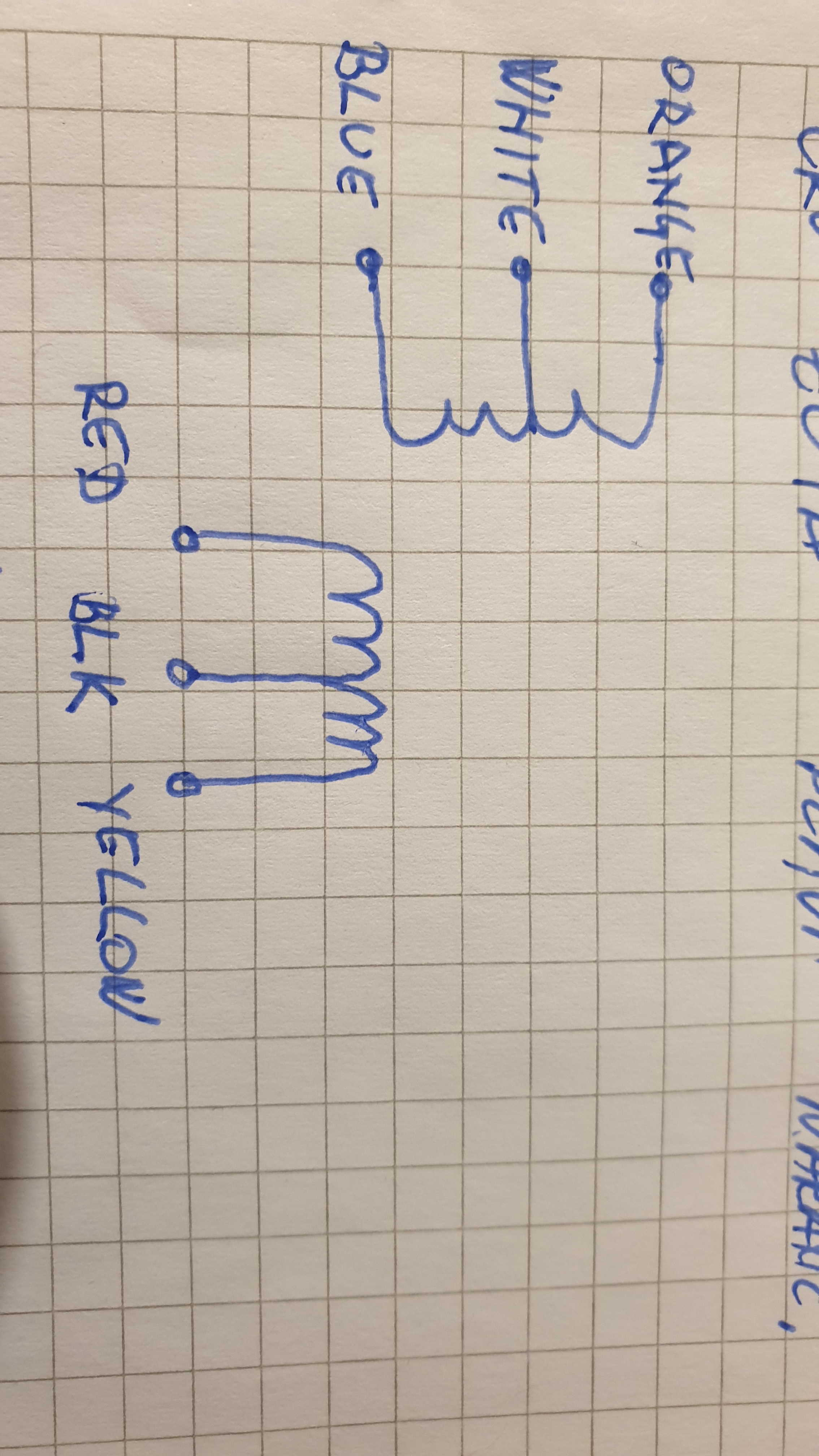
The motor wires are connected by the following schematic:
Coil A:
White - Blue - 1.3 ohm
White - Orange - 1.3 ohm
Blue - Orange - 2.2 ohm
Coil B:
Black - Red - 1.3 ohm
Black - Yellow - 1.3 ohm
Red - Yellow - 2.2 ohm
After this, I had concluded that I made the correct motor connection.
I had tested the A OUT and B OUT pins and got this result:
The maximum voltage is 36V, but my motors are rated for 24V, so it says on their website.
Does the voltage on the output even matter for the stepper?
Should I lower the input voltage by the help of some regulator?
Does the weird noise come from the output FET’s?
The output seems pretty stable, there is a small overshoot on the falling edge, but that is normal, I think
I had filmed the motor in action, and posted the videos on my Google Disk
Thank you for the additional information. As explained in the “FAQs” tab of the 36v4 high-power stepper motor driver product page I linked to in my previous post, the rated voltage for a stepper motor is the voltage at which each coil draws the rated current. So, as long as you are limiting the current to the rated current or below, it is safe to use a higher voltage than the motor is rated for. Using a higher voltage can also have benefits, such as higher achievable step rates.
It looks like the test in the video titled “1000mA” might have missed a couple steps and there is a bit of a knocking noise. Can you still hear that knocking if you lift the motor off the table (e.g. are you sure it is not just the vibrations on the breadboard/surface)?
Have you tried increasing the current limit to the rated current per phase of your motor as I suggested? Can you try it and see if the problem persists? Also, if the knocking noise still happens at the higher current limit, can you try to catch it on video?
By the way, it looks like your scope captures for your power supply were at 20V/div scale, so it might not be as smooth as it appears there. You might want to look at it in AC mode rather than DC mode to get more resolution.
raising the current to 2.5 and 3A (seperate tests)
The motor ran without a problem, but I heard the same sound (the chirping) when I connected the scope probe to the AOUT pin. The ground clip of the probe was connected to the GND pin of the GND lead of the power supply (24V input).
Can EMI cause interference in the driver, resulting in strange sounds in the motor?
Are the steppers susceptible to that?
Regarding your question, I did hear the described noises even when lifting it off the table, they weren’t caused by vibrating items in the vicinity of the motor. The table acts as a soundboard, of course, so the sound is much more intense with the motor being on the table.
Another problem seems to be the power supply. I ordered a new, more powerful transformer which is going to be able to give 24V at full current, without significant voltage drop.
I will post additional information as soon I get the new, improved power supply running. I plan to test the motors under load. How could I monitor the current through the coil, or better yet, is it really necessary, when the IC is doing the current limiting by itself?
If everything seems to be running fine and your application can tolerate the auditory noise, I suspect it should be fine.
As far as EMI, it can be caused by many things (including motors), but we cannot say if that is the source of the noise. If you do not hear the noise at high currents until you connect your scope’s probe, that could be an indication that it is caused by the interference (although, it is not clear if that is what you are describing).
You can measure the current through the coil using a current probe or some kind of current sensor. However, if the system seems to be working, it shouldn’t be necessary.