Hello,
First time using a Pololu motor.
I have a Pololu PL-4845 25D motor with encoder. I’ve used the motor input pins to drive the motor and it’s been working really well. Well, today I tried using the encoder (and I haven’t even connected anything to the 4 pins before) but I couldn’t read the speed. I connected an Arduino UNO’s GND, 5V, A0 and A1 pins to the encoder to analyse the signal (sorry for the blurry image):
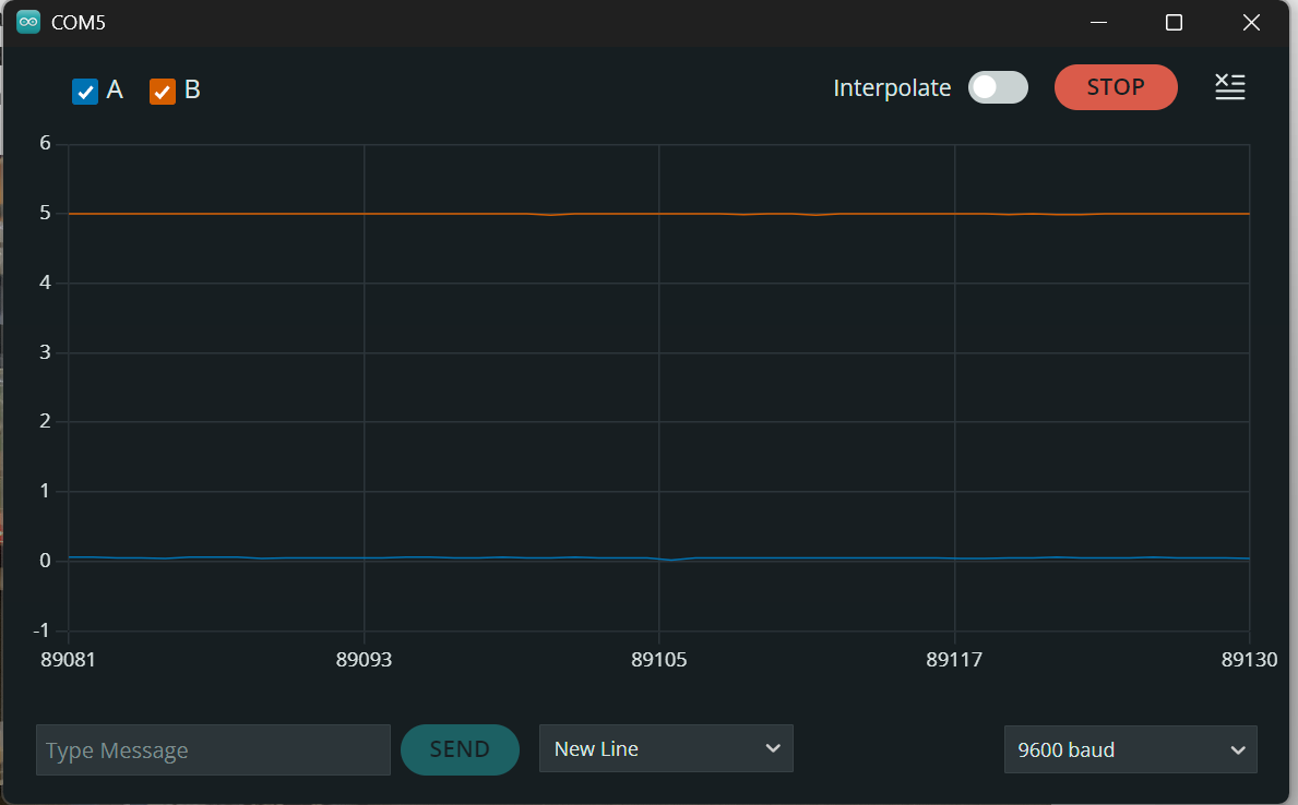
I’ve checked the continuity of all cables from their ends on the side of the encoder. The EVN Alpha located on the top left is only used to power the motor in this test. It uses two 18650 Li-ion cells and DRV8833 IC to drive the motor and can easily power the it. When I power the motor with it and read voltages with the Arduino (Vcc = 4.75V), encoder output A reads 0.05V and output B reads 4.70V relative to GND (green cable), both with Arduino and with a voltmeter. When running the motor the serial plot looks like this:
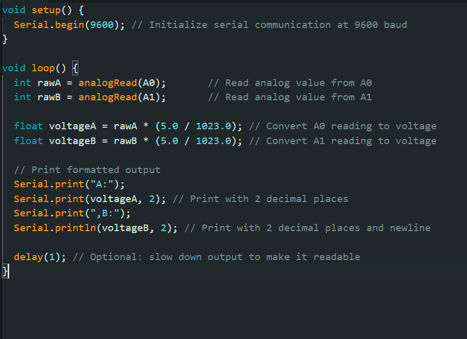
The Arduino’s code is very simple and it works correctly with any other signal:
I can see that the magnet spins when I remove the back cover. The encoder draws a few milliamps of current (around 5-10 mA) from 5v.
Any and all help is appreciated 
Hello.
The encoder outputs are digital signals and when the motor is running at full speed they will be pulsing at a high frequency. There are a lot of time-consuming processes in your code that are probably going to make it unreliable for measuring those signals (e.g. analogRead()`, writing to the Serial Monitor, floating point math, a 1ms blocking delay).
If you just want to verify the signals on the encoder channels, I suggest using a multimeter to measure each of them while you slowly turn the encoder by hand (without the motor powered).
Then, if that works as expected for both encoder channels, you could try using a library like RoatryEncoder that supports interrupts (as shown in the “InterruptRotator” example) to see if that gives you better results.
Brandon
Thanks for the answer,
Even when I read the voltages with a multimeter while slowly turning the motor, I get the same constant values mentioned above. Also when I try using the InterruptRotator example in RotaryEncoder lib it doesn’t sense any rotation when I spin the motor.
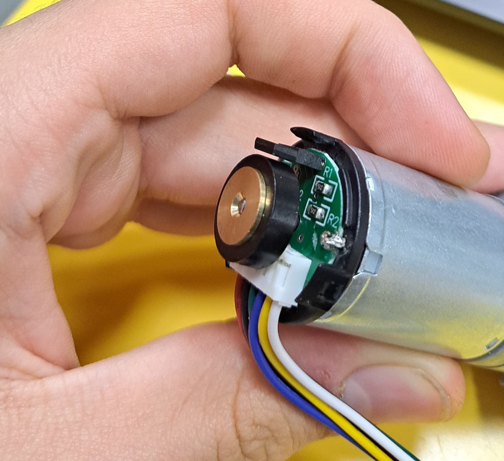
We test every unit, so it was probably working at some point. Could you remove the end cap and post some pictures of the components on the encoder board? In particular, it would be good to verify the spacing of the hall effect sensor (the tall, black rectangular component) relative to the magnetic disc.
Brandon
The encoder board looks like this:
Also I’ve tried using the same testing configuration with another motor with encoder which the encoder looks the same as this one (with a magnet and Hall effect sensor) and it works as intended.
Is there a way to test the sensor directly (e.g. from the solder joints from under the PCB)?
Thanks.
Thank you for the pictures and additional information. It sounds like maybe the encoder has been damaged. Could you email us your order information as well as a reference to this forum post?
Brandon
I’ve bought the motor from a 3rd party so I doubt that Pololu Support will be able to help me.
Thank you.