Hello,
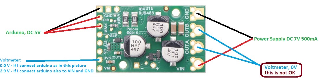
I have problem with Pololu G2 High-Power 24v21. There is no voltage at the OUT A and OUT B. I showed in the picture how I connected it. .
I also tried:
a) connect 5V to SLP
b) connect Power Supply DC 19 V
c) connect only DIR pin, without PWM
d) connect VIN and GND to Arduino (5V)
but it did not help.
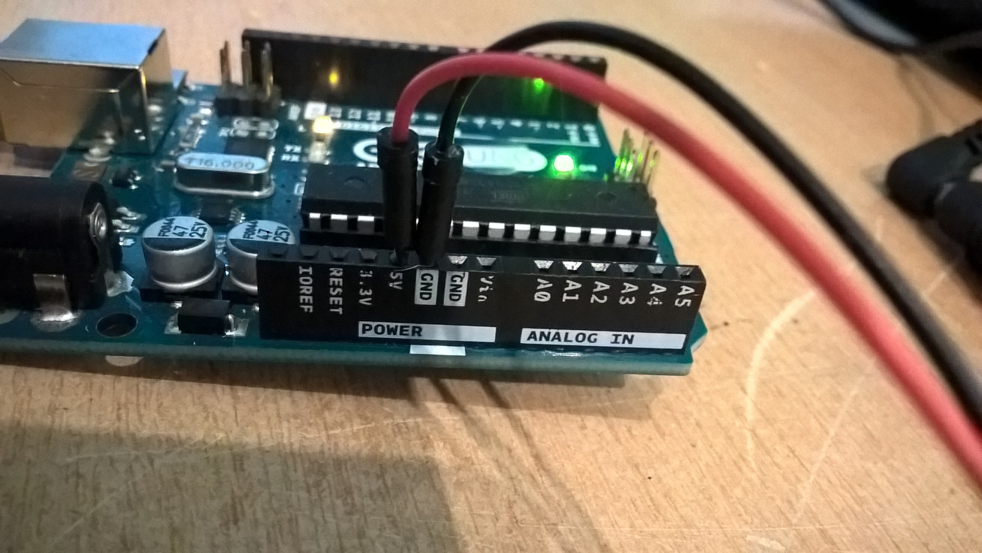
I have read the specification and forum. I checked the solder pins. I checked the voltage of Arduino, it is correct (4.89V). I don’t know if the driver has an LED, but I do not see any light. I was careful when measuring voltage the 3v3 pin, I did not touch the VM pin (I think the touch is not possible, I soldered pin header and inserted the cables).
What do I do wrong?
Best Regards,
Lukas.
Hello, Lukas.
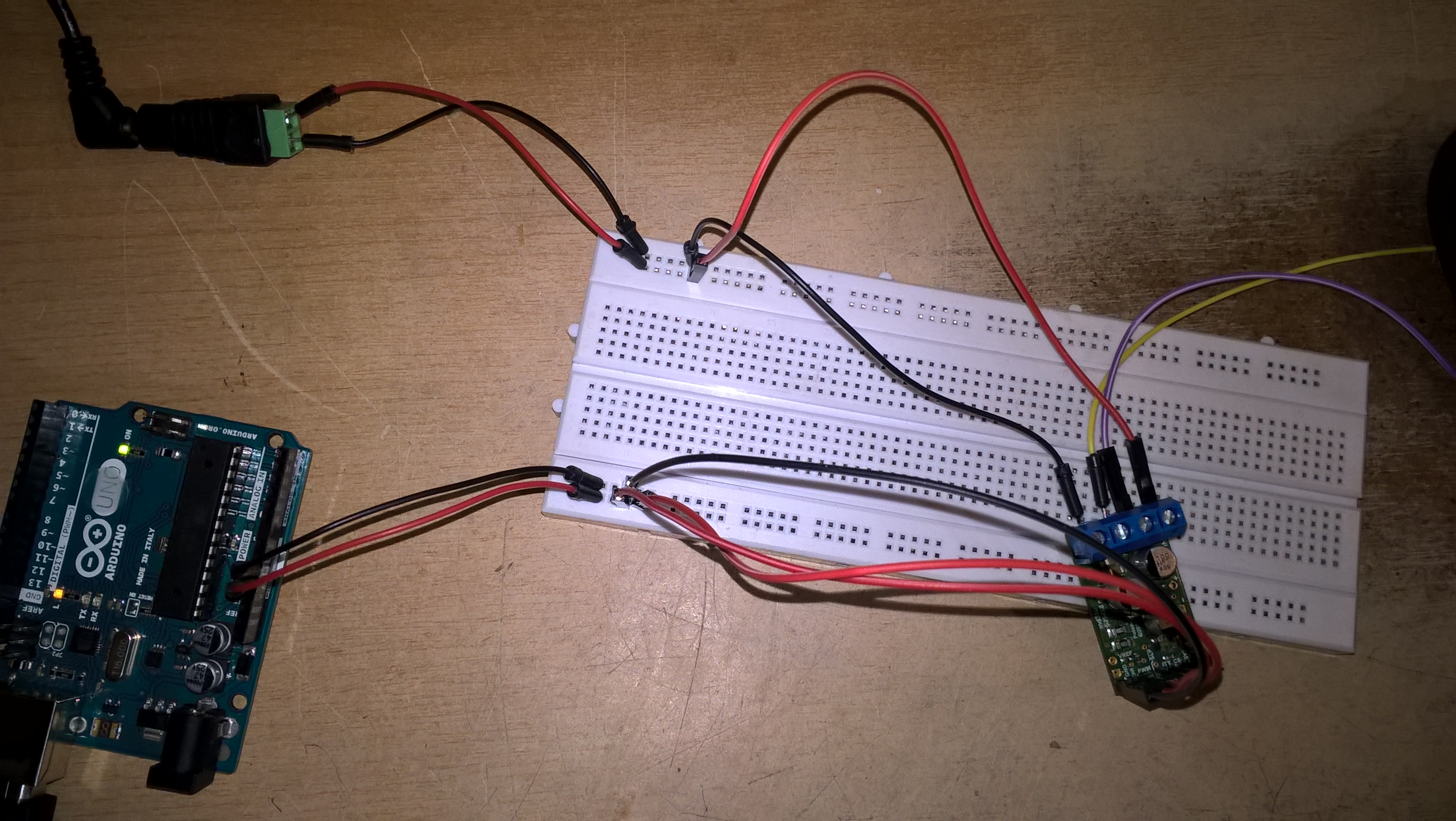
I am sorry you are having trouble with your motor driver. Can you post pictures that clearly show all of the connection in your setup, including your power connections and the connections between the Arduino and driver?
-Jon
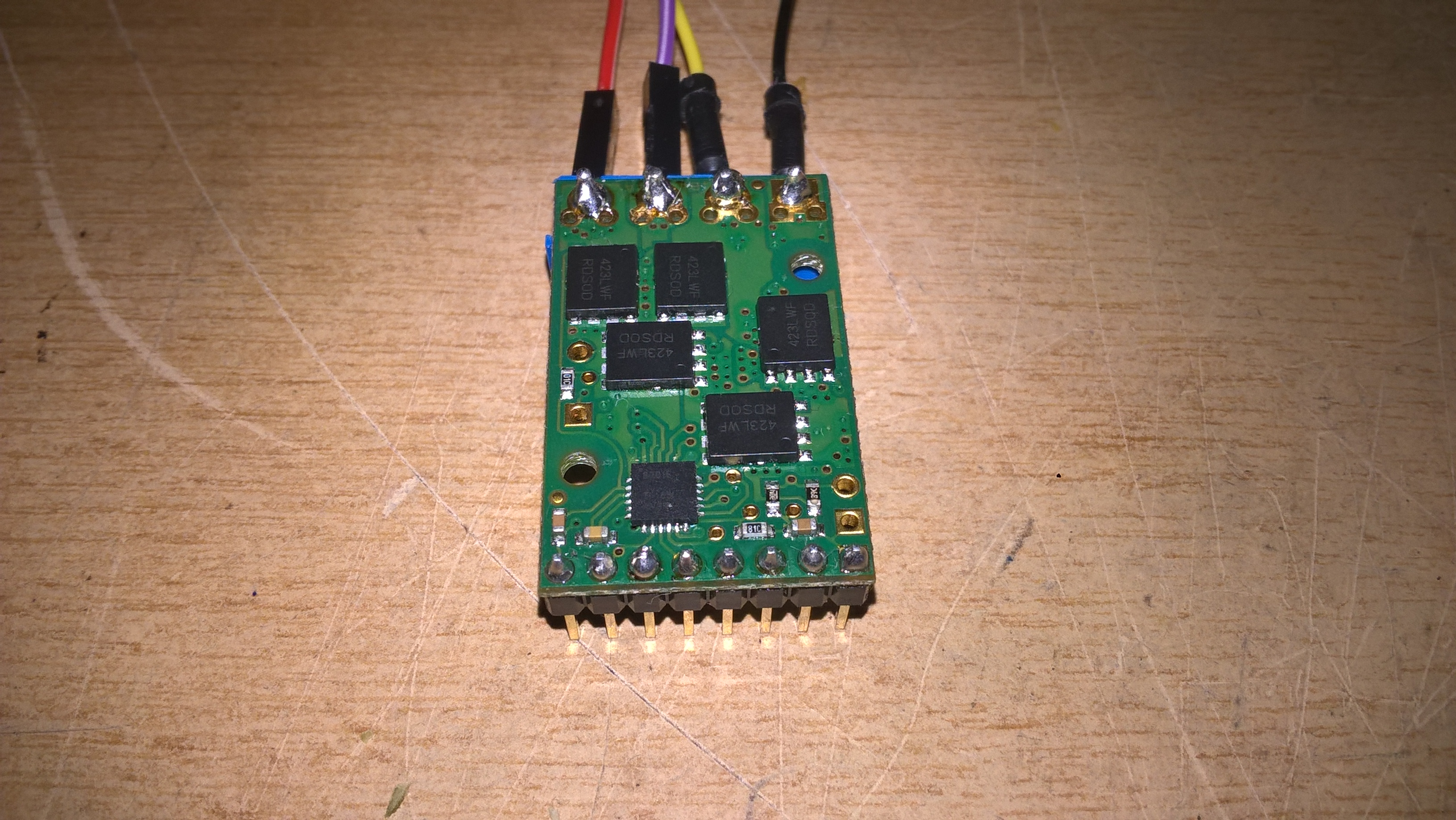
Thank you for the pictures. It looks like the solder on the PWM pin might not be completely wetted or it could be a cold joint. Can you try touching up that connection? You can refer to this visual guide to get a good idea of what an ideal soldering joint should look like.
If things are not working after making that adjustment, can you switch to using your 19V supply? 7V is close to the edge of the lower operating limit for this board, and I want to rule that out as a potential issue. With the 19V supply connected to the setup shown in your pictures, can you measure the voltage on the 3V3 (OUT) and !SLP pins and let me know what values you measure?
By the way, I forgot to mention earlier: there are no lights on the G2 motor driver boards like the one you have.
-Jon
Thank you for your answer. I checked again the solder on the pin PWM pin (and on other pins) using a multimeter, it is correct, 4.89 V.
I connected the power supply 19 V (I checked the power supply, it is working) to VIN and GND, I measured the voltage:
3V3: 0.0V
SLP: 0.5V
When I connected 5V (arduino) to SLP pin:
3V3: 0.2V
SLP: 4.8V
Each time the voltage on OUT A and OUT B pins is 0.0 V.
What do you think about it? Is the driver broken?
Lukas.
It does sounds like something in your board could have been damaged. One last thing you might try is switching around your wiring in your breadboard in case some of the connections are not good. (You can verify that any connections are sound by measuring the voltages at each pin at the board, like looking for 19V at VIN pin on the driver.)
If you email us with salesorder information and refer to this post, we might be able to offer you a replacement.
-Jon