2 Pololu G2 High Power Motor Driver failed - Any advice would be appreciated

Hello!

Recently I’ve run into the issue of a couple of 24v13’s (6.5 to 40V, up to 13A continuous) failing randomly. We are using them to control motors on a robot. A couple days into testing, the first driver failed, and after replacing it with another one, that one failed after around 2 weeks (~1 hour of use per day on average). I do not have the strongest background in electronics (second year engineering student), so I was wondering if someone could look over my setup and help me narrow down what the issue could be before I end up burning through more drivers.

The driver input is from a 22.2V battery, fully charged up before use (So ~25.1V) . I use the drivers to control two motors on each side - both of which are 24V motors. The stall current of each of the motors is 2.85A, so I figured I could drive both wheels off of one driver because even at stall speeds, the motors would draw ~5.7A. Although I do realize that there may be short bursts of currents higher than that stall speed, it should not be a problem (feel free to correct me if I am wrong on this though!).

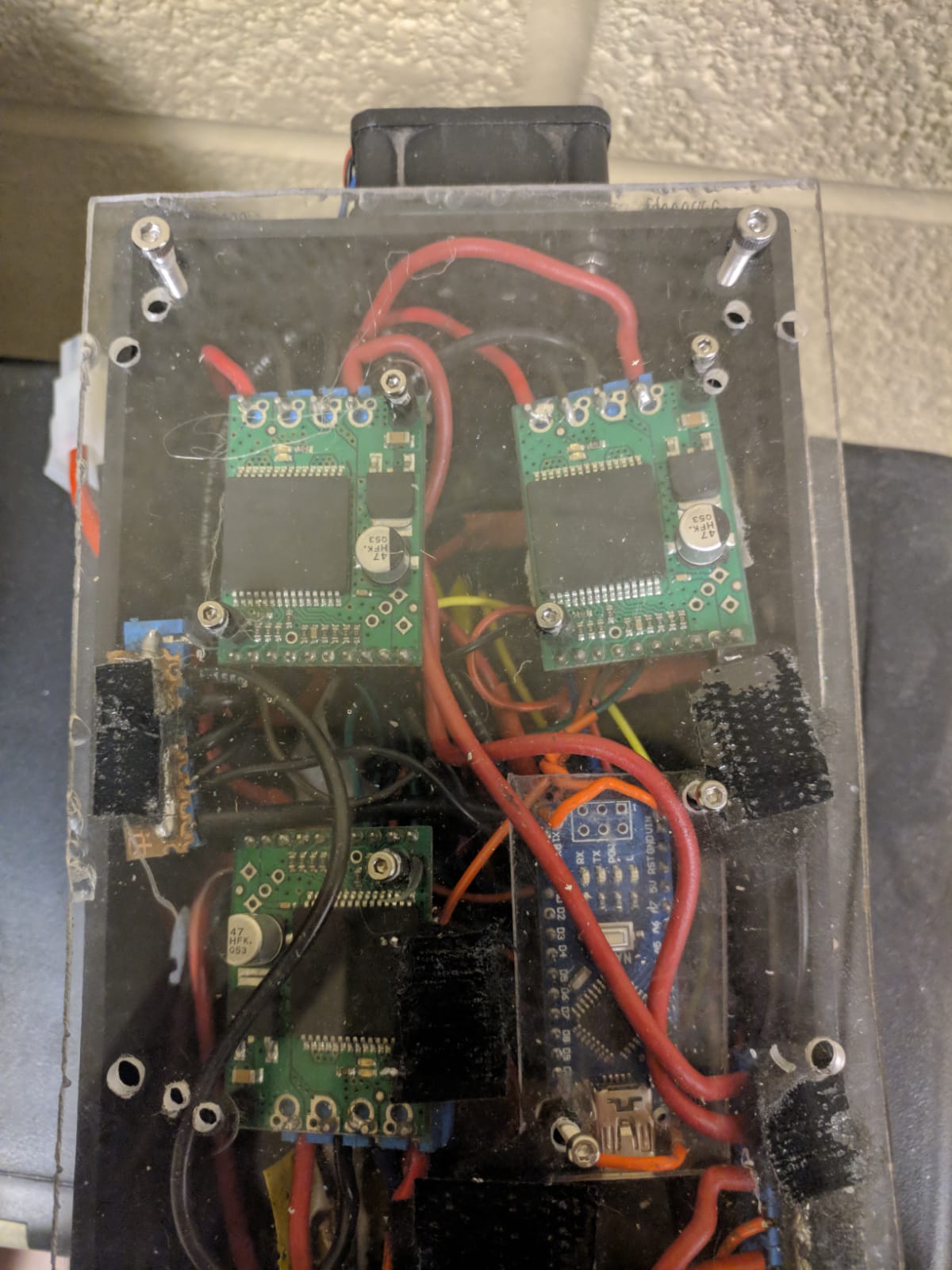
I have soldered two 120uF 50V radial capacitors in parallel , and the drivers are being controlled through an arduino nano. I use 4 pins on the driver - DIR, PWM, SLP & GND. I have ensured that the capacitors are soldered on with the correct polarity. The driver seems to work for a little while on the rover, before completely dying, and not giving any output on the OUTA & OUTB (they give an extremely small reading) when measured with a multi meter.

Temperature is not an issue due to it being in an enclosure that is air-cooled, and because the typical current draw is ~1.6A per motor. The only thing that I can think of that is causing the failure is back-emf from the motors, because the failure seems to occur after the robot has been in motion for a while. Although I haven’t measured the back-emf voltage, it may be larger than what the capacitor can handle. Re-reading the manual states that a capacitor with “a couple hundred uF” should be used, so my next step would be to purchase a 1000uF 50V capacitor and hope that works.

I was wondering if someone who is more knowledgeable than I am can look at my situation and figure out if my assumption is correct. Feel free to let me know if you need any more information about my setup, and any help would be much appreciated. Thanks!

Hello,

The things you describe seem mostly OK. The capacitors you mentioned are a little small, so a bigger one might help, but when supplying a motor driver like that from a battery, the battery can absorb some extra energy if your motor and driver happen to generate some. Are there any diodes or other circuitry in between the battery cells and motor driver that might prevent that from happening?

Is your logic system ever sending logic voltages to the motor driver before the VIN is supplied power? It is generally bad practice to supply signals to something that is not powered since the device could get partially powered through those signal pins which could lead to damage.

What occurred immediately before you noticed the failures? Have you tried connecting one of the failed drivers to a benchtop supply to see if they draw a large amount of current or if any of the components get excessively hot? If you post pictures that show how the components in your system are connected, I can look for any problems.

-Nathan

Hello,

Thanks for the reply. Unfortunately, the original enclosure for it has been taken apart while we troubleshoot this issue, so I can’t provide pictures. However, I have attached a photo of another enclosure that we have, consisting of 3 motor drivers controlling the arm subsystem (running off of 12V). The drive system was hooked up at the exact same way, minus the 5V rail because those drivers have an onboard regulator. I have attached the photo below. I can open the box and take a picture if you’d like, but they would be basically just wires.

Regarding the situation with the logic voltages, we usually power on the motor systems last, after all the electronics have been powered up. However, we do not give any joystick input to it until we are ready to drive up. However, we do not have a system in place to explicitly disable driver operation before the drive power has been turned on.

Regarding the other circuitry between the driver and battery cells, we do not have any diodes or anything in between the circuitry. Not sure if it makes a difference, but we run 2 subsystems on the robot, a 12V and a 24V, and we have a star ground in place to ensure that we do not have grounding issues. Also, the broken drivers doesn’t get hot or anything when connected to a power supply, but I haven’t done current measurements yet.

Right before the failure of the second driver, we ran into one of the wheels being mechanically stuck. We killed power to the robot, disconnected all serial ports and freed the wheel, before attempting to restart the robot. Upon restart, we found that one side of the drive wasn’t working at all, so we ended up physically carrying the robot back to the room.

Since the microcontroller was connected to a laptop (with it’s own internal battery), and the microcontroller shared a common ground with the driver, do you think turning on the driver power on after everything was connected could be an issue, due to another ground being added to the system? I do recall our microcontrollers (arduino nano) resetting after the robot power was turned on (before we even start to drive).

Let me know if you need any other information

Photo of box setup :

How did you characterize the stall current for your motors? Do you have a datasheet for them? If the second motor driver broke when the motors were stalled, that makes it seem like the motors might be drawing too much current through them.

It sounds like your power-up procedure shouldn’t be sending signals before VM is powered, but you might use a voltage divider connected to your microcontroller to detect when the VM pin has power and only allow the logic pins to be sent logic high signals if it is.

USB can power attached devices like a microcontroller, but for the purposes of troubleshooting the motor driver issue, it generally should not matter whether it is USB or some other source powering the microcontroller; though like I mentioned before if the microcontroller is powered and sending logic signals to another part of the system that is not powered like the motor driver, those logic signals might power the other part of the system in a way that causes some kind of damage. By the way, it might be helpful for you to make a diagram of your power system so you can think more about whether something like that is occurring in your system.

-Nathan

Hello,

Yeah, I got the stall current on the motors through the datasheets, and I agree that the symptoms make it seem awfully like an overcurrent/insufficient capacitor issue. I’ll ensure that when we do replace the drivers, we have a protection circuit like that in place so that a control signal does not get sent if VM isn’t powered.

I’ll have a power diagram of the system in a couple days - planning to do some testing on the system to determine if any spikes on voltage occurs on startup when they’re not supposed to.

I’ll keep you guys updated. Thanks for the insight so far!