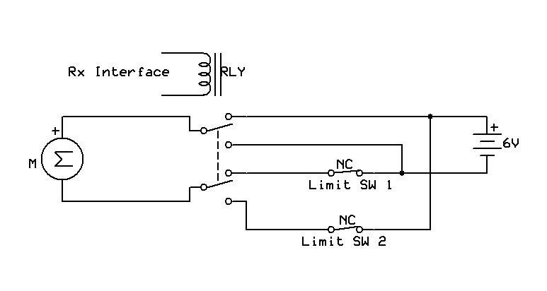
The project I am trying to set up is to run a brushless DC motor as a leadscrew. I have controlled this with a DPDT relay and two SPDT micro sw for the end stops. This works fine but I don’t think the relay will survive in the enviroment it is going to be installed (RC Plane) due to the vibrations - relay bounce
I have therefore got a smc 18v7 which looks to be what I need. Problem being
1: How do I hard wire the micro switches to the A1 and A2 pins. At the moment I have the NC contacts across the + and A1. When testing and actuating the sw NC reads Sw active and when open it reads disconnected and errors. If I select ignore pot disconnect it does not error but when learning it reports back that the values are out of order. Is this because the sw is NC when I require the motor to move? Do I need to wire the sw as NO when I require the motor to run and become NC when it is actuated? Is there a better way to wire the sw to the smc
2: I will be controlling this from my Tx using a channel on a Futaba 617S Rx controlled by a 2 way sw. If I set the input mode to RC input it requires me to connect to RC Channel 1 which is set up as throttle which requires a Neutral, Forward and reverse. The 2 way sw does not have a neutral only full forward or full back. I do not need to set the speed of the motor from the Tx.
If I connect to RC Channel 2 it errors giving RC Channel 1 is invalid.
How do I set it up so I can just use the sw to control the forward and reverse of the motor with limits set by the two micro switches
The original circuit I am using with the relay is attached and if allowed to link to Youtube videos shows the motor in action with the relay to give you some idea of what I require
The Simple Motor Controller cannot control a brushless DC motor; it can only control brushed DC motors. Unfortunately we don’t sell anything for brushless DC motors. However, I would be happy to answer your questions about the limit switches and input settings:
1: If I understand correctly, you want to wire some normally-closed (NC) switches to the Simple Motor Controller and use them as limit switches. Please read the “Limit/Kill Switches” subsection of the “Connecting a Potentiometer or Analog Joystick” section in the Simple Motor Controller User’s Guide and let me know if anything is still unclear to you after reading that.
2: It sounds like you do want to control the speed of the motor using the RC transmitter, but you are limiting yourself to two speeds: full forward and full reverse. In that case, the Quick Input Setup Wizard will not be adequate to set up your input (maybe we should add a feature for that though). You should connect your RC receiver to RC Channel 1 on the SMC. When the wizard asks you to move the RC input to the neutral position, just put it in forward or reverse; it doesn’t matter. Then after you are done with the Quick Input Setup Wizard, you should go the Input Settings tab, select “RC Channel 1”, and change the Neutral Minimum and Neutral Maximum both to 6000 (1500 microseconds).
Apologies the motor is a brushed motor - typo on my part
I eventually found the info and wiring for the limit switches. I am unsure whether to place the 1K - 10K resistor across + and A1/A2 on the inputs. I have it wired them with just the sw across - and A1/A2 and it works OK. In my case would there be any benefit in fitting the resistor?
Speed is going to be set so I do not need to adj from the transmitter. I can do this on initial setup from the control panel. ATM I have set it up to run with a 3 pos sw with neutral in the middle which works. I can stop the motor mid way if necessary if any problems/binding etc. My only problem will be if the micro switches goes permanently closed or fall off but that can only be captured I think if there was a setting for a timeout or including a current cutoff when it binds which this unit doesn’t support. The Jrk supports the current limit but as far as I can tell does not support the way I want to use the limit limit switches, only an encoder/pot method of feedback
Thank you for the info on setting up with a 2 way sw that is a big help
FYI this project is to run a sliding canopy on my latest RC plane build. It’s a 1/8th P47 Razorback Thunderbolt
You either need to add an external pull-up resistor of your own or you need to enable the internal pull-up resistor for the input in the Simple Motor Control Center. Otherwise the line will just be floating when the switch is pressed and it is hard to say what will happen to the voltage on that line.