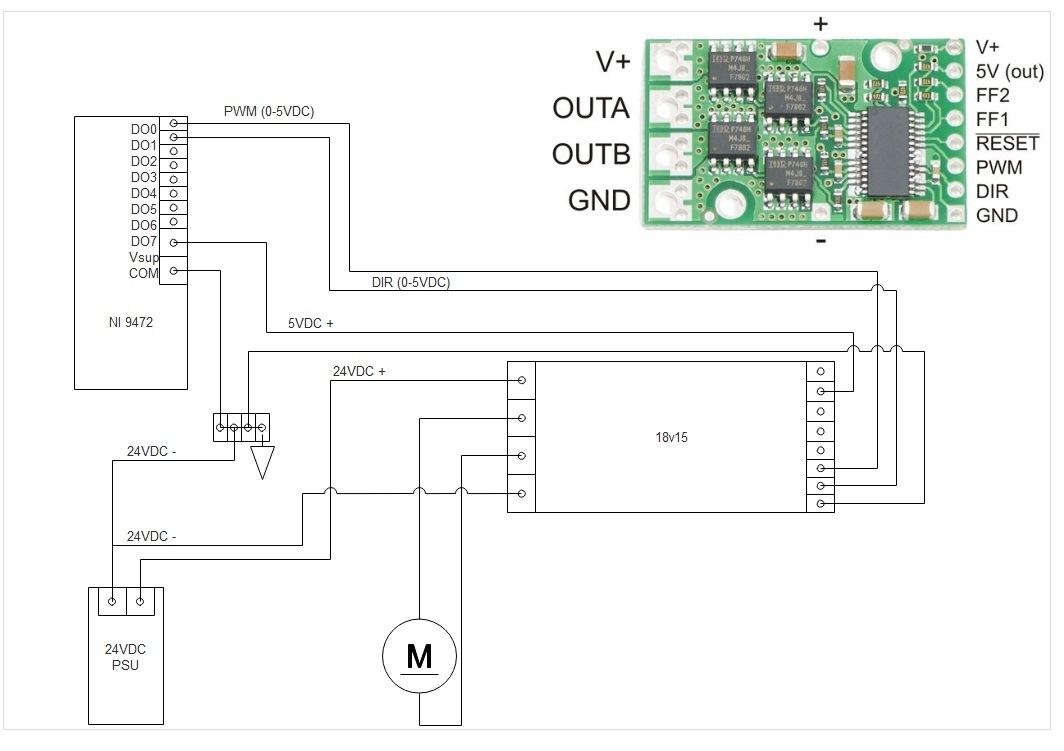
I would like to use the 18v15 motor driver to run a 24VDC motor I have with the NI 9472 generating the PWM signal. I just have a couple questions about how to properly connect it (hardware wise). Can anyone please take a look and let me know if my proposed wiring is correct? If not can anyone please steer me in the right direction?
18v15 Wiring
High Power Side
V+ : Wire to +24VDC PSU
GND: Wire to -24VDC (common) PSU
OUTA: Wire to Motor
OUTB: Wire to Motor
Logic Side
5V OUT: Wire to Vsup on NI 9472
PWM: Wire to DO0 on NI 9472
DIR: Wire to DO1 on NI 9472
GND: Wire to common ground
NI 9472
DO0: Wire to PWM on 18v15
DO1: Wire to DIR on 18v15
Vsup: Wire to 5V OUT on 18v15
COM: Wire to common ground
NI 9472 DO0 would be PWM output & DO1 would be high/low for direction.
Questions?
Do I just send a PWM signal from the NI controller to the PWM pin on the 18v15? I’m guessing the motor is then controlled by this input PWM signal on the logic side of the controller?
Can all common/grounds be attached to one another. IE. on both the 24VDC & 5V logic side?
Your diagram mostly looks fine. Yes, you should be able to send a PWM signal to the PWM pin of the 18v15. The grounds on the 18v15, like all of our other motor drivers, are internally connected. (In general, all your devices should usually share a common ground.)
The one issue i see with your diagram is that since the 18v15’s 5V (out) pin cannot supply much current (a few milliamps at most), and drawing too much current from it can permanently damage the board, we recommend finding a separate 5V supply to power your NI 9472. Also, 24V is close enough to the maximum rated input voltage of the 18v15 that voltage spikes could be an issue, so you should make sure to solder in the included electrolytic capacitor.
Thank you for the information. I will source a separate 5V for the 9472. What are the 5V out pins typically designed for on the 18v15 motor drivers? Also is there a min amperage needed for the PWM/DIR on the motor driver?
Also on the 9472 this is a PnP transistor. The module itself is powered by a separate power source. I was basically going to route the 5V out from the 18v15 through DO1 and DO2 back to the 18v15. There really should be no load as it should just be going through the PnP transistor on the ni 9472 then back to the 18v15 driver as a PWM or open/close relay for the DIR.
The driver IC has an internal 5V regulator output that is available on one of its pins, so we just pass that on to the user. Like I mentioned in my last reply, it can only supply a few milliamps, so it is typically most useful for powering pull-ups to make logic high signals. If you are sure the PNP circuit has an appropriately low current draw, then you should be able to use the 5V out pin the way you proposed. The PWM/DIR pins are just high impedance digital inputs, so they will not draw an appreciable amount of current; however, there is a 47kΩ pull-down on the PWM pin, which will draw around 100μA when it is driven high.