Hello, I’m having an issue with my 12v12 motor controller and the 5v out. The 5v out and ground are powering a potentiometer who’s signal I’m using as an analog voltage input to the RX line. When I have the USB connection active trying to configure the input and feedback voltages, the main 5v out has continuity with the GND. This is only the case when the USB cable is connected to my computer. I cannot find any continuity without the board powered on, so I’m not sure where else to look for wiring errors.
Obviously then I’m unable to configure feedback or input correctly because of the voltage issue. Any ideas? Try a different USB cable? Unsolder my connections and start over?
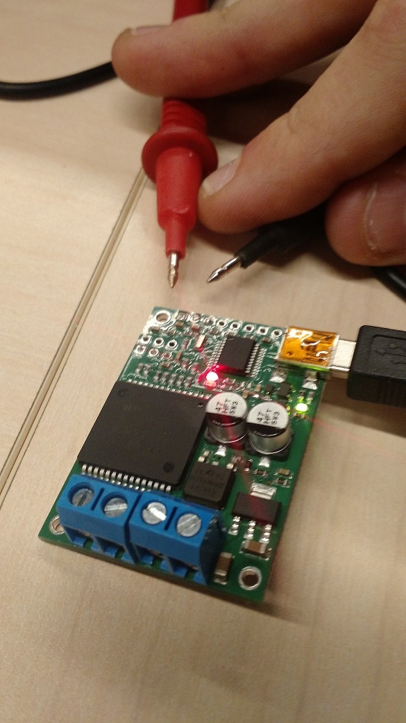
That sounds like a strange problem. If GND is shorted to 5V, all the LEDs on the jrk should be off and the USB software would not work at all; is that the case when you plug in the USB? Can you post some pictures that show all of your connections as well as a picture showing how you are measuring the continuity? Another thing that might could cause a problem like that is if the USB cable has a short in it, so you might try a different one like you suggested.
Picture is attached, I’m testing continuity bxt the bottom two solder pads (GND and 5V). I get continuity bxt GND and 5v, but I also get 4.7 V across those 2 pads, and I also get 4.7 V across RX and GND, and 0 V across 5V and RX.
The USB software is working just fine. As shown and as I’m trying to use it (analog voltage input), the input is showing 4095 with nothing connected to it. If I change it to serial input mode, the input goes to 0. This is a second USB cable that I’ve tried now. As you can see I decided to desolder all my connections to keep troubleshooting this.
From your description, I suspect you might have your leads swapped so your GND probe is on the 5V pin and the positive probe is on the GND pin. If you swap the leads so that your GND probe is connected to the GND pin, you should not measure continuity. There are diodes involved in the circuit, so this is normal.
The RX pin is pulled-up internally, so when nothing is connected, it will go to a default behavior of high.
I do not see anything abnormal with what you are measuring; is the board working correctly or doing something unexpected when you try to use it?
Hmmm, ok, I’ll check the probes tomorrow. What I need to do now is test the
potentiometer i was trying to use, this could have all been started by that
not working correctly. I’ll pull that out and bench test it separately.
I could not get the board to respond to moving my pot, that’s what started
the investigation. I disconnected it and tested voltage at the pot
connector and found 5v on the signal (rx) line. Which I thought was wrong,
but sounds normal from what you say. I wonder if the internal pullup is
doing something to the sensor I’m using?
The pull-up resistor on the RX pin should not interfere with your potentiometer signal. If your potentiometer is working correctly, there could be other reasons such as configuration settings that would stop the motor from moving. Are you using any feedback? If not, you might want to check that the feedback mode (found in the “Feedback” tab of the Jrk Configuration Utility) is set to “None”. If you are using feedback, you should double check that your proportional value is not set to 0.
If you are still having problems getting your motor to react to your potentiometer input, you can post your jrk settings file here, and I would be glad to look further into it. You can save your jrk settings file by selecting the “Save settings file…” option within the “File” drop-down menu of the Jrk Configuration Utility.
Alright, so as you suspected, if I swap GND probe to 5V I do not get
continuity. I won’t be able to get the pot tested till this weekend. I was
attempting to use feedback and will double check the proportional value. If
I can’t get it working this weekend I’ll post the settings file. Thanks.
To follow up, I don’t have a completely functioning board yet, but I’m getting there. I’m using a pot that has 2 different circuits built in, with supposedly separate power/gnd inputs. However, when testing it, I had to power both sensor circuits to get a signal voltage out of either of them. Lesson learned on that one. I’m getting it wired correctly and I’ll post back here if I have more problems.