That will generate bus errors on the I2C bus. SDA going low when SCL is high is a START condition, and SDA transitioning to high while SCL is high is a STOP condition.
I tend to not want to use D11-13, as I tend to leave my programmer hooked up. On the other hand, this leaves the serial port pins (D0/D1) free I also have two digital Sharp obstacle sensors right now, doing wall hugging/collision avoidance. So… D0,1,2,3,5 A0,2,3. That makes for exactly 6 line sensors and two obstacle avoiders, so theoretically, I’m good. Also, the user switch pin can probably be multi-purposed as well. Use the switch to turn on the program, use RESET to turn it off Also possibly D11.
I actually soldered a second row of pin headers on the outside of the Arduino headers, so I can hook up to any Arduino pin using a female jumper cable or plug, or a test clip. I recommend this to anyone using this shield, and thanks for putting those extra rows of pads in there!
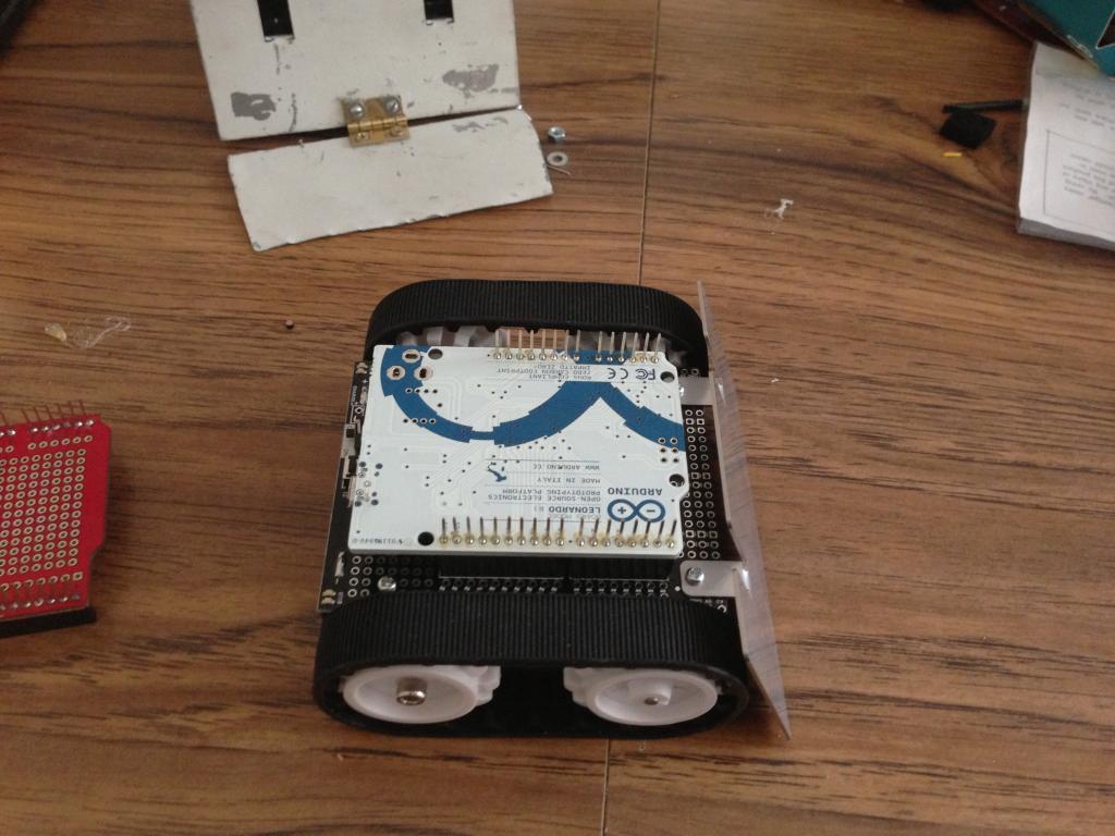
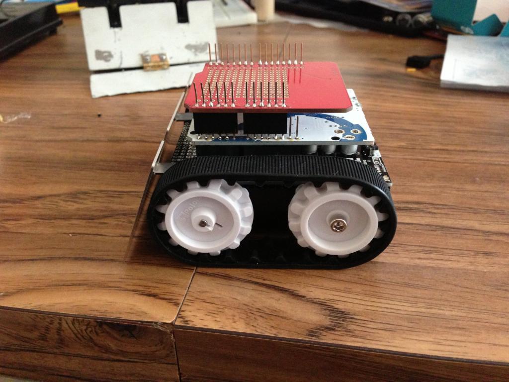
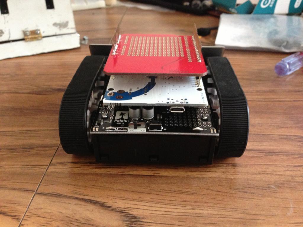
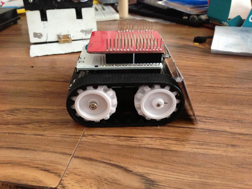
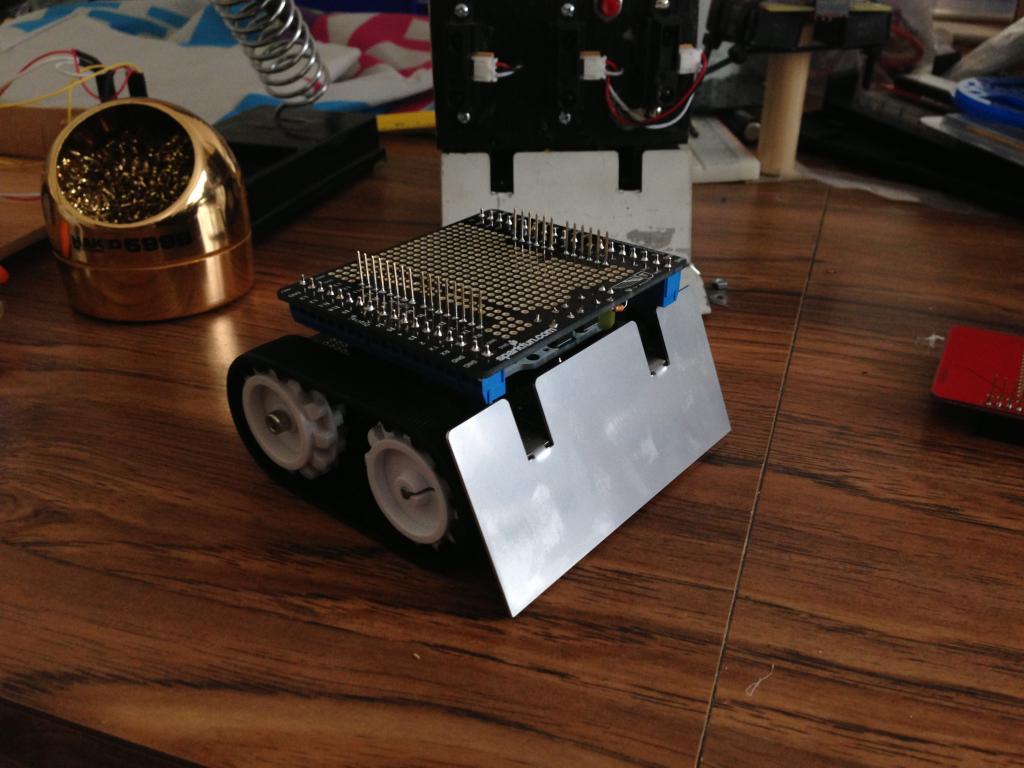
Ok, received my Leonardo without headers from Adafruit today, soldered on the headers I had gotten from Pololu previously, and took a couple pics to show the setup with an additional shield stacked on top to give you guys an idea of what it would look like… (I plan to build a full on enemy detection shield to put on the top this spring…)
Just the Leonardo board, notice the header pins still existing so we can stack more shields in the other direction!
Cool mako, it’s coming along good. I received my Zumo on Thursday, and
have been thinking of how to build it up. No plan to use it for mini-sumo
here, mainly software dev.
Another shield that may be of interest is the Seeed Studio Protoshield. It’s
somewhat bigger than the others, and sticks out on one end. Not good for
mini-sumo, but may be useful for mounting sensors on the end and still
allowing more shields to be stacked. $10 at Radio Shack.
Never hurts to throw a cap across the terminals of a motor, as this tends to reduce noise feedback. I usually don’t bother though and haven’t had any problems…
The shield does have some motor dampening caps built-in.
The motor controller on the shield is somewhat sensitive to larger capacitors and will easily to into overcurrent shutdown if you use something like a 100 nF (or perhaps even 10 nF) cap across the motor yourself. It works well if you don’t add any capacitor yourself, but just use the ones built-into the shield.
FWIW: I have mine modded with 1300 mAh 2S LiPo power, modded the voltage sensor to work with the LiPo range (de-soldering R10,) two 10 cm Sharp digital distance sensors (for left/right wall sense) and a 6-way QTR-8RC line sensor under the shield. I’m thinking I could write a program with four modes, for maze solving, line following, sumo, and general exploration. Sadly, I’m out of I/O for any kind of user interface other than the button and the LED.
The I2C is still available for that, though. I’m sure something can be done
Btw: It would be cool if the front shield connectors had some connector layout (similar to the analog port + power/ground on front left/right) that made SDA, SCL, 5V and GND available.
jwatte was dead-on in his answer to this one: the shield has integrated 3.3 nF caps across the motor terminals. We originally tried larger caps, but they triggered the motor driver’s overcurrent protection and led to poorer performance. I do not recommend adding any extra capacitors across the motor terminals.
No, you should never need to add lubrication to the gearbox.
Thanks Ben and jw. I’m about ready to build up the Zumo now.
Decided to mount the Arduino board on 3/4" standoffs, as it’s not one of the
standard boards [home brew], and I need clearance for the XBee module.
This only adds an extra 1/4" to the normal height. Will install long male
headers on the Zumo shield.
Then, fiberboard on short standoffs for a spacer-mount, then mount the
Digilent uC32 right side up, and a proto shield for sensors on top of that.
Will still be pretty short.
jw, you might look at using ribbon cable to connect to your sensors, as
the wire gauge is smaller and it’s easier to work with physically. I use
ribbon cable all over my bots.
after reading some threads about the Zumo and reading the Pololu website I decided to give the Zumo a try. Although I’m very new to electronics, Arduino and Pololu I must say that I got it all together pretty quickly and without too much problems. It’s the first time I got myself an electronics kit and soldering tip for these tiny bits. I’ve never soldered a jumper, button, switch or header before (also see problem 2 ) but this was pretty easy to do. A third hand is a very useful tool!
Problems I’ve had are:
Two screws are just a bit too short to assemble the chassis, spacer and shield. Fortunately I had a few lying around so I could finish the assembly.
Buzzer jumper installation was not entirely clear (even though I was bit stupid here as well ). Silly me installed a jumper over all three available connections while further down the manual it says I just needed to solder a jumper over two holes. Probably a “Duh” to most of you but I made this mistake.
The disassembly of the chassis is not difficult but one step in the process is a bit tricky: I couldn’t find a good way to get the wheel off the motor. I felt I had to push (too) hard to get it off. I managed to get it off but with applying a little too much force to my liking.
Now on to installing the reflectance sensors . That’ll be the next step, then on to the Sharp optical range finder and/ or the integrated compass/ accelerometer. I quite like building this litle robot so far so I’m very excited to get it running across a line
About the compass/ accelerometer: Pololu makes some remarks on the accuracy of these sensors on the shield.
Has anybody used these sensors with any success?
And to the Pololu guys: in the user’s guide you wrote “We plan to provide some higher-level example code in the near future to demonstrate how a Zumo robot might be able to make use of this data.”. I’m not that far yet but I’m looking forward to see some usefull applications for the Zumo
I just finished my install and it appears I didn’t do enough research before installing the reflectance sensors, so I hope this message helps you out. If you got the recommended QTR-1RC sensors, the “optimal” distance for the sensors is 3mm, and max is 9.5mm. You won’t be able to mount those that close to the ground without extra hardware. I would recommend buying some of these (https://www.pololu.com/catalog/product/1013) 1x3 pin female stackable headers and mounting those underneath the shield where the sensors go, and then plugging the headers that you soldered onto the sensor boards into that. At least, that is my plan.
I installed the reflectance sensors today and I also came up with this problem. I soldered the header onto the shield and the sensor right onto that. The sensors react to different reflectance but only closer to the sensor than I mounted them now. I also noticed that adding light will give better results (my surface isn’t really white but off-white).
I decided to try adding some light to the sensor and I soldered a resistor and a LED in series. I also soldered them on the expansion part of the shield between 5V and Ground with the resistor on the 5V side.
HERE’S MY nOOb question: Why doesn’t the LED light up in this connection?
Bringing the sensor down physically will be a better solution so I’ll go with that idea as well. Nevertheless I still don’t know why my LED doesn’t work…
What value is the series resistor for the LED? What color is the LED? At 5 volts, a value between 470 and 100 ohms is used. 330 or 220 ohms is usually the best choice. I think the light from the LED could interfere with the sensors performance. So don’t think LED is a good idea.[o][/o] If you are using the QTR-1RC sensor or similar, the maxium sensing distance is under a half an inch. I assume you are using a black running surface for the Zumo, and a white ring around the outside to stop and reverse.
Hello, Michael (somerwil). If your LED isn’t turning on at all, you probably connected the LED backwards or used a resistor that is much too large. 1000 Ohms would be good.
You’ve probably figured it out by now, but the different Arduino boards
have the PWM signal that drives the buzzer coming out on different pins.
328P is the standard Aruino UNO or Duemilanove. Necessary to get the [nicely
written] buzzer examples to work properly. FWIW, it would probably work
ok with either board with both jumpers installed, as the tone would only
be coming out 1 pin, and the other pin should be set as input by default
[I think].
Also, the buzzer is a magnetic device, and not a piezo, so you don’t want
your s.w. holding the buzz pin high for long periods of time.
Also, when using the Sharp IR rangers, take note of the “fold-back” of
the response curve at short distances.
Yeah, Led hooked up backwards is the usual reason they don’t light up.
However, are you using a visible or IR Led? I doubt a visible Led will
have much effect on the pickup by the photoreflector, since it uses IR,
and an IR Led will likely interfere with the pickup, so maybe not a good
idea, like donde said. But you can play with it and see what happens.
The included screws should be long enough to mount the shield to the chassis when using the thinner spacer included with the shield (as opposed to the thicker spacer included with the chassis). The shield also includes two longer screws that should be used in the front if you are going to be mounting a Zumo blade.
Soldering male header pins to all three buzzer jumper locations isn’t really a problem. You can still put the shorting block across the two pins appropriate for your Arduino, and if you ever use a different Arduino, you have the option to move the shorting block.
I have played around with these some. I think you might be able to use the accelerometer to tell where you have been impacted by an opposing sumo bot if you can filter the signal appropriately, and the compass can be used for basic navigation in environments without too much magnetic noise.
I don’t think we have any such high-level examples in the works right now, but it helps to know people out there are waiting for them. Please feel free to keep the pressure on!
BTW, the following may be of interest. I have been thinking of how I
want to hook up some bumper switches on my Zumo base, and for
another project I bought this LCD shield.
If you check the schematic, it has a neat way to attach several SPST
switches to 1 ADC channel. I’ve seen other schemes before, but this one
is fairly new to me.
thanks for the quick replies! I got the Zumo up and running now including my LEDs (just messed up 5V and Ground ). I’ll start a new topic about that so you can see my progress.
Back to the Zumo shield comments: I only noticed one type of spacer plates. Those are probably the thick ones so I needed some longer screws. I used the two longer bolts (which where intended to use on the Zumo plate) and two of my own screws. No big deal, perhaps an idea to add a few extra (4 will do) in the kit.
The higher level examples is not something I came up with, it’s in the user’s guide
There should have been a 2-piece spacer with the Zumo shield, and a
1-piece spacer as part of the regular base. The 2-piece has large cutouts
which go around the solder joints on the Zumo shield. The 1-piece spacer
will clash against the solder joints on the Zumo shield unless you use
additional spacers, like washers, as I ended up doing after I broke the
2-piece spacer.

 ) but this was pretty easy to do. A third hand is a very useful tool!
 ). Silly me installed a jumper over all three available connections while further down the manual it says I just needed to solder a jumper over two holes. Probably a “Duh” to most of you but I made this mistake.
 . That’ll be the next step, then on to the Sharp optical range finder and/ or the integrated compass/ accelerometer. I quite like building this litle robot so far so I’m very excited to get it running across a line
