
Want to add the GP2Y0D810Z0F Sharp sensor to the front the Zumo. Since its off by 90 on two axis’ looks like a servo cable and some kind of homemade bracket are called for. Anybody come up with an elegant solution? Pics would be nice.
What is best mount position of the GP sensor, horizontal or vertical on a moving robot?
I’m going to try 2 GP2Y0A21YK0F sensors, one on each end of a strip of 1/8" plywood, 1/2" x 5". It will be mounted on Arduino
Leonardo board, using the 2 holes at front near the bulldozer plate. I’ll use 2 very short spacers to just clear the board.
Then, I’ll use the difference of distance of each sensor to the object, and turn the robot accordingly and change speed. Not sure how the sketch code will look like yet, but seems simple enough. The first part I can do, no problem! 
According to the datasheets, it’s actually better to mount the Sharp rangers
vertically, that way they’ll range vertical edges better when the Zumo is
rotating horizontally [turning].
Also, it takes the Sharps about 50-msec to update a new reading, as they
apparently average several successive readings. Therefore, if the robot is
moving fast it can get spurious readings.
I saw the data sheet, but it seemed unclear, for it didn’t show horizontal mounting as “incorrect”. 2 vertical mountings were shown incorrect. I do now see why the correct vertical would be right. And that’s what I did. The Sharp senses distance between 10 and 15 cm, backs up and then spins a few times, and continues. I also got Zumo to stop using millis() after a minute.
This is a great reminder that you’re on a 16bit system; If you use a 16 bit integer to hold the value of millis(), you’ll wrap after 65535 milliseconds, which is a little over a minute. This is a common pattern for repeating an operation at a lower frequency than your main loop:
#define LOOP_DELAY 10
int ping_delay = 100;
uint32_t lastPing = millis();

void loop()
{
  if (millis() >  ping_delay + lastPing){
    lastPing = millis();
    float cm = sonar.ping_cm();

    Serial.print("sonar: "); Serial.println(cm);
    ...
  }

  delay(LOOP_DELAY);
}
The key is to use 32 bit integers for holding values from millis()
Or always do comparisons to differences and constants. What you want is this:
unsigned short lastMillis = 0;

unsigned short now = millis();
if (now - lastMillis > MY_INTERVAL) {
    lastMillis = now;
    do_the_thing();
}
The difference here is that unsigned two’s complement math will wrap, and as long as MY_INTERVAL is 60 seconds or less, and you call this code at least once every 5 seconds, it will work fine!
From figures 6+7 of the GP2Y0A21YK0F d/s, you can infer from symmetry what
would be the best targets for horizontal mounting. Vertical orientation is shown
as preferred for sensing vertical edges and for horizontal panning/movements,
therefore take the opposite for horizontal mounting.
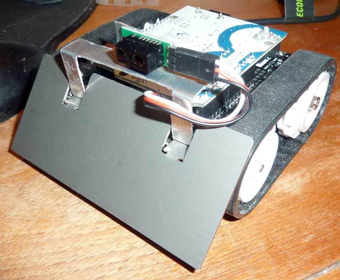
I ended up doing a simple little bracket out of a piece of aluminum sheet from bigbox_homestore. Single Sharp pointing straight ahead. Horizontal (but could be flipped any time). Used a servo pigtail to connect. Won’t win any fabrication awards but it works…
So the thread jump about milliseconds confuses me. Why can’t you just read the digital pin in a delay loop?
In other words…this seems to work fine for me:
ZumoBuzzer buzzer;
void setup() {}

void loop(){
  if (digitalRead(4) == LOW)
    buzzer.playNote(NOTE_G(3), 200, 15);
  delay(100);
}Sorry, didn’t mean to derail the thread; I just wanted to point out that quite often “it stops working after 65 seconds” corresponds to 16 bits worth of milliseconds.
Johnelle, the pattern I described is useful when you want to poll multiple inputs at different intervals.
For example check for button press every 10ms, but poll your range finder every 50ms.
Then you could set your timer loop for 10ms delay, and compare millis() and lastPing + 50ms so you only call that sensor every fifth time through the loop.