
Am using Intel Edison with zumo robots. I have difficulty calibrating the Zumo Reflectance Sensor Array . With the libraries installed and compiled, the sensor is on but not working properly with abnormal values. Have connected A0 to A5 properly to Edison.
Hello.
It sounds like you are using our Zumo Robot for Arduino with your Edison. Can you confirm that? Can you post pictures that show all of your connections, including soldered joints? Can you post a sample of the data you are getting that is abnormal? How are you using the sensors when you generate that data (e.g. are you waving any specific object in front of the array while your code is running)?
Our library uses standard Arduino functions to operate the sensors, but we have not tested them on the Edison and there is no guarantee that those functions will execute in the exact same manner on non-AVR processors like that. However, I can try to help you troubleshoot the problem and maybe modify the code to work with the Edison if necessary.
-Nathan
yes. Am using Zumo Robot for Arduino with your Edison. To calibrate the sensors, I have pasted a black tape on a piece of white paper. No any sort of object is being waved.
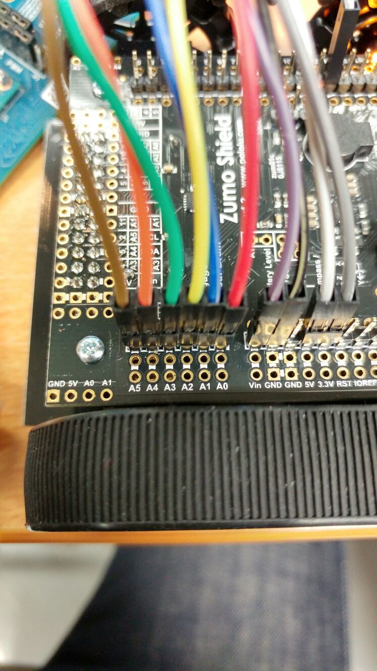
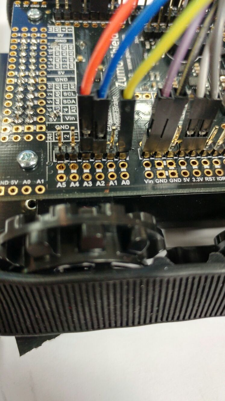
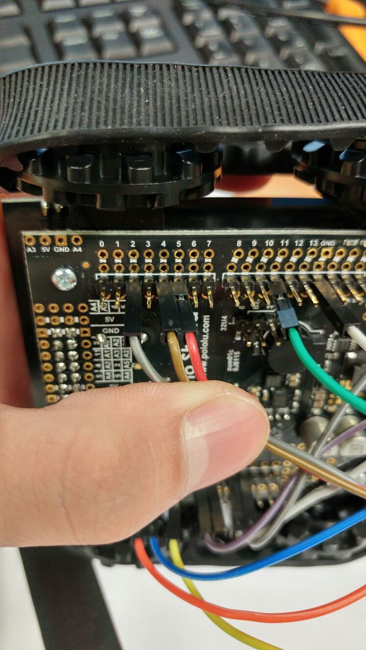
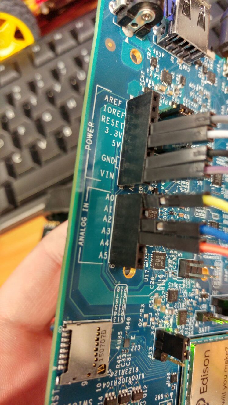
Connection is simple but am actually unsure. Connected Pin 7,8,9,10,12,13 for Motors and A0,A1,A2,A3,A4,A5 for sensors to Intel Edison. Cannot upload image as it is too big. Is there any other way?
Below is the data i got.
0 113 127 128 0 0
0 117 130 133 0 0
0 1000 1000 1000 0 0 2000
0 1000 1000 1000 0 0 2000
0 1000 1000 1000 0 0 2000
0 1000 1000 1000 0 0 2000
0 1000 1000 1000 0 0 2000
0 1000 1000 1000 0 0 2000
0 250 1000 1000 0 0 2333
0 1000 1000 1000 0 0 2000
0 1000 1000 1000 0 0 2000
0 1000 1000 1000 0 0 2000
0 1000 1000 1000 0 0 2000
0 1000 1000 1000 0 0 2000
0 1000 1000 1000 0 0 2000
.
.
.
.
0 1000 1000 1000 0 0 2000
0 1000 1000 1000 0 0 2000
0 1000 1000 1000 0 0 2000
0 1000 1000 200 0 0 1636
0 1000 1000 1000 0 0 2000
0 1000 333 1000 0 0 2000
Thank you.
Can you try reducing the size of the photos before uploading them or uploading them to an image hosting service and posting the links here?
Are you sliding all of the sensors over both the black tape and white paper during the sensor calibration?
-Nathan
Yes. I did slide the all the sensors over the black tape and white background slowly.
I will try uploading the picture .
Thank you.+

i connected a two pins wrongly and have amended it(see the above picture). Have different but still weird results
2000 5 2000 6 6 5
2000 4 2000 2000 2000 4
0 0 0 1000 1000 0 3500
0 0 0 0 0 0 5000
0 0 0 1000 1000 0 3500
0 0 0 1000 1000 0 3500
0 0 0 1000 1000 0 3500
0 0 0 1000 1000 0 3500
0 0 0 1000 1000 0 3500
0 0 0 1000 1000 0 3500
0 0 0 1000 1000 0 3500
0 0 0 1000 1000 0 3500
0 0 0 1000 1000 0 3500
0 0 0 0 0 0 5000
0 0 0 1000 1000 0 3500
0 0 0 1000 1000 0 3500
0 0 0 0 0 0 5000
0 0 0 0 0 0 5000
0 0 0 0 0 0 5000
0 0 0 1000 1000 0 3500
0 0 0 1000 1000 0 3500
0 0 0 0 0 0 5000
0 0 0 0 0 0 5000
0 0 0 1000 1000 0 3500
0 0 0 1000 1000 0 3500
0 0 0 1000 1000 0 3500
0 0 0 1000 1000 0 3500
0 0 0 1000 1000 0 3500
0 0 0 1000 1000 0 3500
0 0 0 1000 1000 0 3500
0 0 0 1000 1000 0 3500
0 0 0 1000 1000 0 3500
0 0 0 1000 1000 0 3500
0 0 0 1000 1000 0 3500
0 0 0 1000 1000 0 3500
0 0 0 1000 1000 0 3500
0 0 0 1000 1000 0 3500
0 0 0 1000 1000 0 3500
0 0 0 1000 1000 0 3500
0 0 0 1000 1000 0 3500
0 0 0 1000 1000 0 3500
0 0 0 0 0 0 5000
0 0 0 1000 1000 0 3500
0 0 0 0 0 0 5000
0 0 0 1000 1000 0 3500
0 0 0 0 0 0 5000
0 0 0 1000 1000 0 3500
0 0 0 0 0 0 5000
0 0 0 1000 1000 0 3500
Hello.
By default, our Zumo shield does not connect the line sensors to A0 - A5. The pins for the reflectance sensor array are listed in the “Adding a Zumo reflectance sensor array (optional)” section of the Zumo Shield User’s Guide, which is linked to on the “Resources” tab of the shield’s product page. You might try moving your jumper wire connections on the Zumo shield and the Edison to the pins mentioned in the user’s guide.
-Nathan
Hello.
Have tried the above link connection before. Tried it again and got a result slightly different from what i remember but still have got a couple of sensors not working. Using ZumoReflectanceSensorArray library “sensor calibration” downloaded from Github.
Below is the code
#include <QTRSensors.h>
#include <ZumoReflectanceSensorArray.h>

/*
This example is designed to be run an Arduino that is connected to a Zumo
Reflectance Sensor Array through a Zumo Shield.

The setup phase of this example calibrates the sensor for ten seconds and
turns on the pin 13 LED while calibration is going on.  During this phase,
you should expose each reflectance sensor to the lightest and darkest
readings they will encounter.  For example, if you are making a line
follower, you should slide the sensors across the line during the
calibration phase so that each sensor can get a reading of how dark the
line is and how light the ground is.  Improper calibration will result in
poor readings. If you want to skip the calibration phase, you can get the
raw sensor readings (pulse times from 0 to 2500 us) by calling
reflectance.read(sensorValues) instead of
reflectance.readLine(sensorValues).

The loop function reads the calibrated sensor values.  It also uses the
values to estimate the position of a line, in case you are using the Zumo
for line following. It prints the sensor values to the serial monitor as
numbers from 0 (maximum reflectance) to 1000 (minimum reflectance) followed
by the estimated location of the line as a number from 0 to 5000.  A line
position of 1000 means the line is directly under sensor 1, 2000 means
directly under sensor 2, etc.  0 means the line is directly under sensor 0
or was last seen by sensor 0 before being lost.  5000 means the line is
directly under sensor 5 or was last seen by sensor 5 before being lost.
*/

ZumoReflectanceSensorArray reflectanceSensors;

// Define an array for holding sensor values.
#define NUM_SENSORS 6
unsigned int sensorValues[NUM_SENSORS];

void setup()
{
  reflectanceSensors.init();

  delay(500);
  pinMode(13, OUTPUT);
  digitalWrite(13, HIGH);        // turn on LED to indicate we are in calibration mode

  unsigned long startTime = millis();
  while(millis() - startTime < 10000)   // make the calibration take 10 seconds
  {
    reflectanceSensors.calibrate();
  }
  digitalWrite(13, LOW);         // turn off LED to indicate we are through with calibration

  // print the calibration minimum values measured when emitters were on
  Serial.begin(9600);
  for (byte i = 0; i < NUM_SENSORS; i++)
  {
    Serial.print(reflectanceSensors.calibratedMinimumOn[i]);
    Serial.print(' ');
  }
  Serial.println();

  // print the calibration maximum values measured when emitters were on
  for (byte i = 0; i < NUM_SENSORS; i++)
  {
    Serial.print(reflectanceSensors.calibratedMaximumOn[i]);
    Serial.print(' ');
  }
  Serial.println();
  Serial.println();
  delay(1000);
}

void loop()
{
  // read calibrated sensor values and obtain a measure of the line position.
  // Note: the values returned will be incorrect if the sensors have not been properly
  // calibrated during the calibration phase.
  unsigned int position = reflectanceSensors.readLine(sensorValues);

  // To get raw sensor values instead, call:
  //reflectanceSensors.read(sensorValues);

  for (byte i = 0; i < NUM_SENSORS; i++)
  {
    Serial.print(sensorValues[i]);
    Serial.print(' ');
  }
  Serial.print("    ");
  Serial.println(position);

  delay(250);
}
and got this result
2000 5 5 5 5 5
2000 4 4 5 2000 4
0 0 0 0 1000 0 4000
0 0 0 0 0 0 5000
0 0 0 0 0 0 5000
0 0 0 0 1000 0 4000
0 0 0 0 1000 0 4000
0 0 0 0 0 0 5000
0 0 0 0 0 0 5000
0 0 0 0 0 0 5000
0 0 0 0 0 0 5000
0 0 0 0 0 0 5000
0 0 0 0 0 0 5000
0 0 0 0 0 0 5000
0 0 0 0 1000 0 4000
0 0 0 0 1000 0 4000
0 0 0 0 1000 0 4000
0 0 0 0 1000 0 4000
0 0 0 0 1000 0 4000
0 0 0 0 1000 0 4000
0 0 0 0 1000 0 4000
0 0 0 0 1000 0 4000
0 0 0 0 1000 0 4000
0 0 0 0 0 0 5000
0 0 0 0 0 0 5000
0 0 0 0 0 0 5000
0 0 0 0 0 0 5000
Can you try running the QTRRCRawValuesExample to see if you the raw sensor values change as you move the sensor array over the black tape on your white background? You will need to change the number of sensors and the pins on your Edison board those sensors are connected to in the code.
Once you have tried this, can you post the modified code, the sensor output with a description of how you are moving the robot, and pictures that show your revised connections?
-Nathan
the values do change but by a little. Really little. Have change the number of sensors to 6 and connected the pins according to the code.
The code and pin connection:
#include <QTRSensors.h>

// This example is designed for use with eight QTR-1RC sensors or the eight sensors of a
// QTR-8RC module.  These reflectance sensors should be connected to digital inputs 3 to 10.
// The QTR-8RC's emitter control pin (LEDON) can optionally be connected to digital pin 2,
// or you can leave it disconnected and change the EMITTER_PIN #define below from 2 to
// QTR_NO_EMITTER_PIN.

// The main loop of the example reads the raw sensor values (uncalibrated).
// You can test this by taping a piece of 3/4" black electrical tape to a piece of white
// paper and sliding the sensor across it.  It prints the sensor values to the serial
// monitor as numbers from 0 (maximum reflectance) to 2500 (minimum reflectance).


#define NUM_SENSORS   6     // number of sensors used
#define TIMEOUT       2500  // waits for 2500 microseconds for sensor outputs to go low
#define EMITTER_PIN   2     // emitter is controlled by digital pin 2

// sensors 0 through 7 are connected to digital pins 3 through 10, respectively
QTRSensorsRC qtrrc((unsigned char[]) {3, 4, 5, 6, 7, 8},
  NUM_SENSORS, TIMEOUT, EMITTER_PIN);
unsigned int sensorValues[NUM_SENSORS];


void setup()
{
  delay(500);
  Serial.begin(9600); // set the data rate in bits per second for serial data transmission
  delay(1000);
}


void loop()
{
  // read raw sensor values
  qtrrc.read(sensorValues);

  // print the sensor values as numbers from 0 to 2500, where 0 means maximum reflectance and
  // 2500 means minimum reflectance
  for (unsigned char i = 0; i < NUM_SENSORS; i++)
  {
    Serial.print(sensorValues[i]);
    Serial.print('\t'); // tab to format the raw data into columns in the Serial monitor
  }
  Serial.println();

  delay(250);
}
the results:
5	5	5	5	5	5
5	5	5	5	5	5
5	5	5	5	5	5
5	5	5	5	5	5
5	5	5	5	5	5
5	5	5	5	5	5
5	5	5	5	5	5
5	5	5	5	5	5
6	6	6	6	6	6
5	5	5	5	5	5
5	5	5	5	5	5
5	5	5	5	5	5
5	5	5	5	5	5
5	5	5	5	5	5
5	5	5	5	5	5
5	5	5	5	5	5
5	5	5	5	5	5
5	5	5	5	5	5
5	5	5	5	5	5
5	5	5	5	5	5
5	5	5	5	5	5
5	5	5	5	5	5
5	5	5	5	5	5
5	5	5	5	5	5
5	5	5	5	5	5
5	5	5	5	5	5
6	6	6	6	6	6
5	5	5	5	5	5
5	5	5	5	5	5
5	5	5	5	5	5
6	6	6	6	6	6
6	6	6	6	6	6
5	5	5	5	5	5
5	5	5	5	5	5
6	6	6	6	6	6
6	6	6	6	6	6
5	5	5	5	5	5
5	5	5	5	5	5
5	5	5	5	5	5
6	6	6	6	6	6
53	53	53	53	53	53
5	5	5	5	5	5
5	5	5	5	5	5
6	6	6	6	6	6
5	5	5	5	5	5
When shown with white, value of 5 is displayed and 6 is displayed when it’s over the black tape. Move the robots slowly across the tape in perpendicular(like a line following robot) and in parallel .
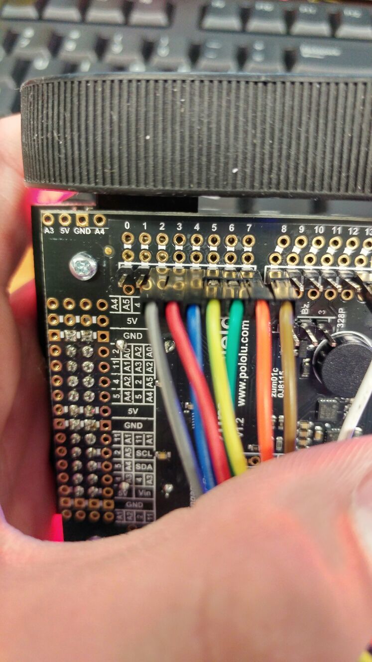
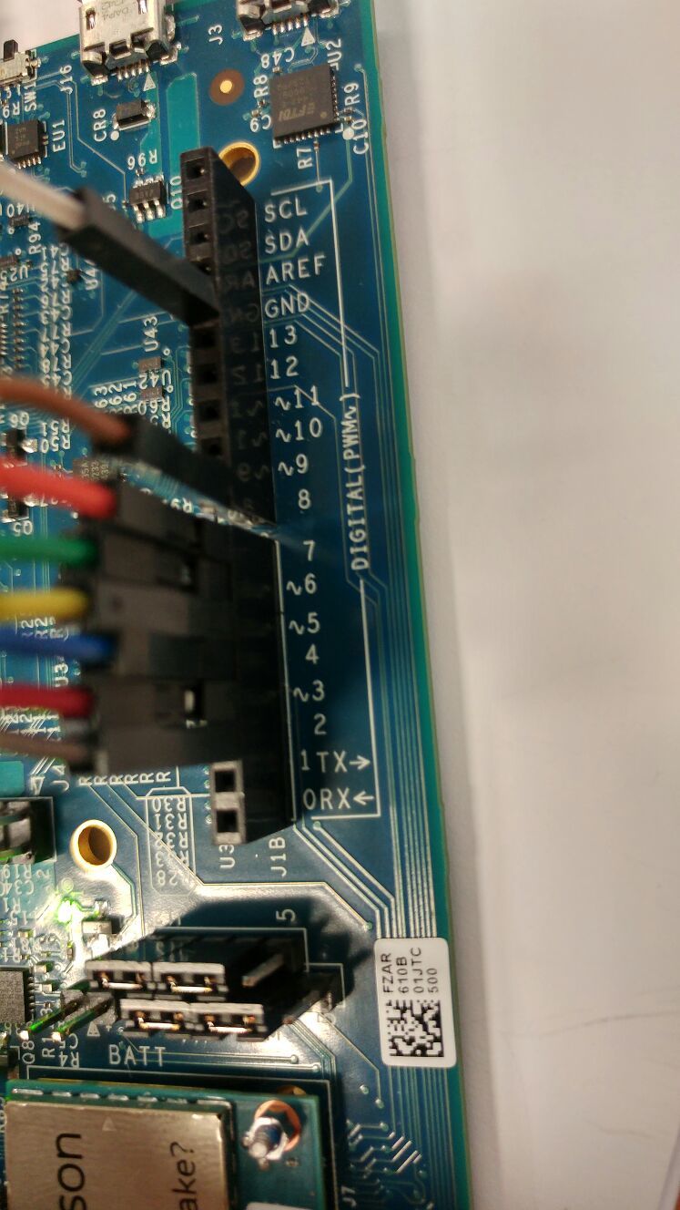
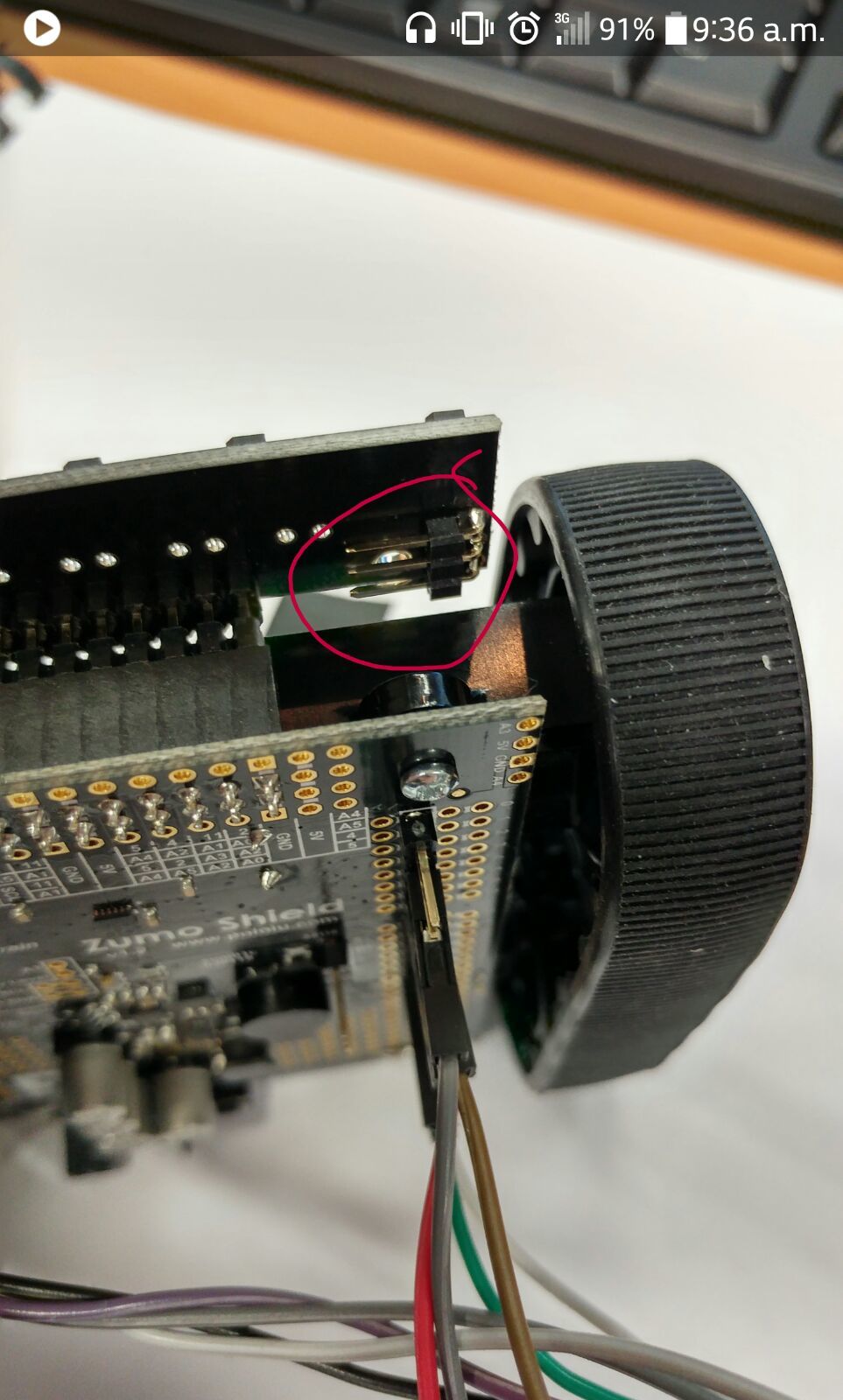
Thanks for the update. The QTR sensors are on pins 5, A2, A0, 11, A3, and 4 (this is documented in the Adding a Zumo reflectance sensor array (optional) section of the User’s Guide I pointed you to the other day). This is a physical connection so you will need to plug your wires into those specific pins on the Zumo Shield. Can you connect those pins on the shield to the corresponding pins on your Edison and change the declaration line in your code to:
QTRSensorsRC qtrrc((unsigned char[]) {5,A2,A0,11,A3, 4 }, NUM_SENSORS, TIMEOUT, EMITTER_PIN);Also, it looks like you might have GND on your Edison connected to pin 13 of the Zumo shield. You should connect it to GND on the Zumo shield.
There should be a right angle header on the top right side of the QTR sensor board. If there is a jumper installed there, can you remove it?
Once you have made those changes, can you try to run QTRRCRawValuesExample code again?
-Nathan
Made changes accordingly and have better results. But it still does’nt seems right to me.
The Code
#include <QTRSensors.h>

// This example is designed for use with eight QTR-1RC sensors or the eight sensors of a
// QTR-8RC module.  These reflectance sensors should be connected to digital inputs 3 to 10.
// The QTR-8RC's emitter control pin (LEDON) can optionally be connected to digital pin 2,
// or you can leave it disconnected and change the EMITTER_PIN #define below from 2 to
// QTR_NO_EMITTER_PIN.

// The main loop of the example reads the raw sensor values (uncalibrated).
// You can test this by taping a piece of 3/4" black electrical tape to a piece of white
// paper and sliding the sensor across it.  It prints the sensor values to the serial
// monitor as numbers from 0 (maximum reflectance) to 2500 (minimum reflectance).


#define NUM_SENSORS   8     // number of sensors used
#define TIMEOUT       2500  // waits for 2500 microseconds for sensor outputs to go low
#define EMITTER_PIN   2     // emitter is controlled by digital pin 2

// sensors 0 through 7 are connected to digital pins 3 through 10, respectively
QTRSensorsRC qtrrc((unsigned char[]) {5,A2,A0,11,A3, 4 },
  NUM_SENSORS, TIMEOUT, EMITTER_PIN);
unsigned int sensorValues[NUM_SENSORS];


void setup()
{
  delay(500);
  Serial.begin(9600); // set the data rate in bits per second for serial data transmission
  delay(1000);
}


void loop()
{
  // read raw sensor values
  qtrrc.read(sensorValues);

  // print the sensor values as numbers from 0 to 2500, where 0 means maximum reflectance and
  // 2500 means minimum reflectance
  for (unsigned char i = 0; i < NUM_SENSORS; i++)
  {
    Serial.print(sensorValues[i]);
    Serial.print('\t'); // tab to format the raw data into columns in the Serial monitor
  }
  Serial.println();

  delay(250);
}
The results
5	5	5	5	5	2500	2500	2500
6	6	6	6	6	2500	2500	2500
5	5	5	5	5	2500	2500	2500
5	5	5	5	5	2500	2500	2500
7	7	7	7	7	2500	2500	2500
5	5	5	5	5	2500	2500	2500
5	5	5	5	5	2500	2500	2500
5	5	5	5	5	2500	2500	2500
5	5	5	5	5	2500	2500	2500
6	6	6	6	6	2500	2500	2500
5	5	5	5	5	2500	2500	2500
5	5	5	5	5	2500	2500	2500
6	6	6	6	6	2500	2500	2500
5	5	5	5	5	2500	2500	2500
5	5	5	5	5	2500	2500	2500
5	5	5	5	5	2500	2500	2500
6	6	6	6	6	2500	2500	2500
6	6	6	6	6	2500	2500	2500
6	6	6	6	6	2500	2500	2500
5	5	5	5	5	2500	2500	2500
5	5	5	5	5	2500	2500	2500
6	6	6	6	6	2500	2500	2500
5	5	5	5	5	2500	2500	2500
5	5	5	5	5	2500	2500	2500
5	5	5	5	5	2500	2500	2500
5	5	5	5	5	2500	2500	2500
6	6	6	6	6	2500	2500	2500
5	5	5	5	5	2500	2500	2500
5	5	5	5	5	2500	2500	2500
6	6	6	6	6	2500	2500	2500
5	5	5	5	5	2500	2500	2500
The new connection

Is this the right angle header you were talking about? have removed the Jumper
It looks like you have the hardware connections in a good state now. The code that runs the sensor is contained in our QTRSensors library, which can be found in the \libraries\QTRSensors folder of your Arduino sketchbook location. Can you try editing the QTRSensors.cpp file in that path and swapping lines 433 and 434?
Original:
        digitalWrite(_pins[i], HIGH);   // make sensor line an output
        pinMode(_pins[i], OUTPUT);      // drive sensor line high
Revised for Edison:
        pinMode(_pins[i], OUTPUT);   // make sensor line an output
        digitalWrite(_pins[i], HIGH);      // drive sensor line high
Please note that the comments in the original file are reversed. The revised code here has the comments on the correct lines.
Also, when you post your results here, could you please use code tags to format them? You can look at how we have modified your previous posts for examples of how to use code tags.
-Nathan
Not able to access Visual Studio as license is expired. So edited the cpp files with note pad.
2500	5	5	5	5	5
2500	6	6	6	6	6
2500	6	6	6	6	6
2500	5	5	5	5	5
2500	5	5	5	5	2500
2500	7	7	7	7	2500
2500	6	2500	6	6	2500
2500	5	2500	5	5	2500
2500	5	2500	5	5	2500
2500	5	2500	5	5	2500
2500	6	2500	6	6	2500
2500	6	2500	6	6	2500
2500	5	2500	5	5	2500
2500	6	2500	6	6	2500
2500	5	2500	5	5	2500
2500	5	2500	5	5	2500
2500	5	2500	5	5	2500
2500	6	2500	6	6	2500
2500	5	5	5	5	5
2500	5	5	5	5	5
2500	6	6	6	6	6
2500	5	5	5	5	5
2500	5	5	5	5	5
2500	6	6	6	6	6
2500	5	5	5	5	5
2500	5	5	5	5	5
2500	6	6	6	6	6
2500	5	5	5	5	5
2500	5	5	5	5	2500
2500	5	2500	5	5	2500
2500	6	2500	6	6	2500
2500	5	2500	5	5	2500
2500	6	2500	6	6	2500
2500	5	2500	5	5	2500
2500	5	2500	5	5	2500
2500	6	2500	6	6	2500
2500	5	2500	5	5	2500
Is that how code tag work?
Hello, zaqwerty.
Thank you for trying that modification to the library. We have heard from a couple of other cases where customers are having problems using the Intel Edison with our QTR-RC reflectance sensors as well. I suspect there is some difference with the Edison board that make our library incompatible or the sensor impractical to use with it; it might be that the Edison’s operating system is unable to do the precise I/O timing needed to operate the sensors.
You might have better luck posting on the Intel Edison forum to see if they can offer additional suggestions. If any other forum members here have successfully used the QTR-RC reflectance sensors with the Edison, please let us know.
By the way, your code tags were almost correct. You can use [code] to specify where your code starts and [/ code] (without the space) to specify where it ends. I have edited your most recent post to include these tags.
Brandon
Alright. Thank you for all the help and patience provided.
Thanks Nathan and Brandon!