I just put my zumo kit together (with and UNO) and am trying to get the reflectance array working. I soldered all 24 pins and have gotten the calibration code to run but it doesn’t seem like it is reading anything. I am just getting:
All of the LEDs (e.g. the six infrared LEDs and the two red LEDs) on the reflectance sensor array are on by default. So, if the LEDON jumper is not connected then the reflectance sensor array’s two red LEDs should be on. If the LEDON jumper is connected, then whichever GPIO is connected (either pin 2 or A4) will be able to control whether or not the LEDs are off or on. Also, if you are connecting the reflectance sensor array to your Zumo Shield, VIN should measure about 7.45V, not 5V, and especially not -5V.
The results you are getting in the Arduino serial monitor when running the SensorCalibration sketch are identical to what you would get if the sensor array was not connected to the Zumo Shield. This, combined with the fact that your LEDs are not turning on and that you are measuring a voltage on VIN that we do not expect make this seem like a connection or soldering issue.
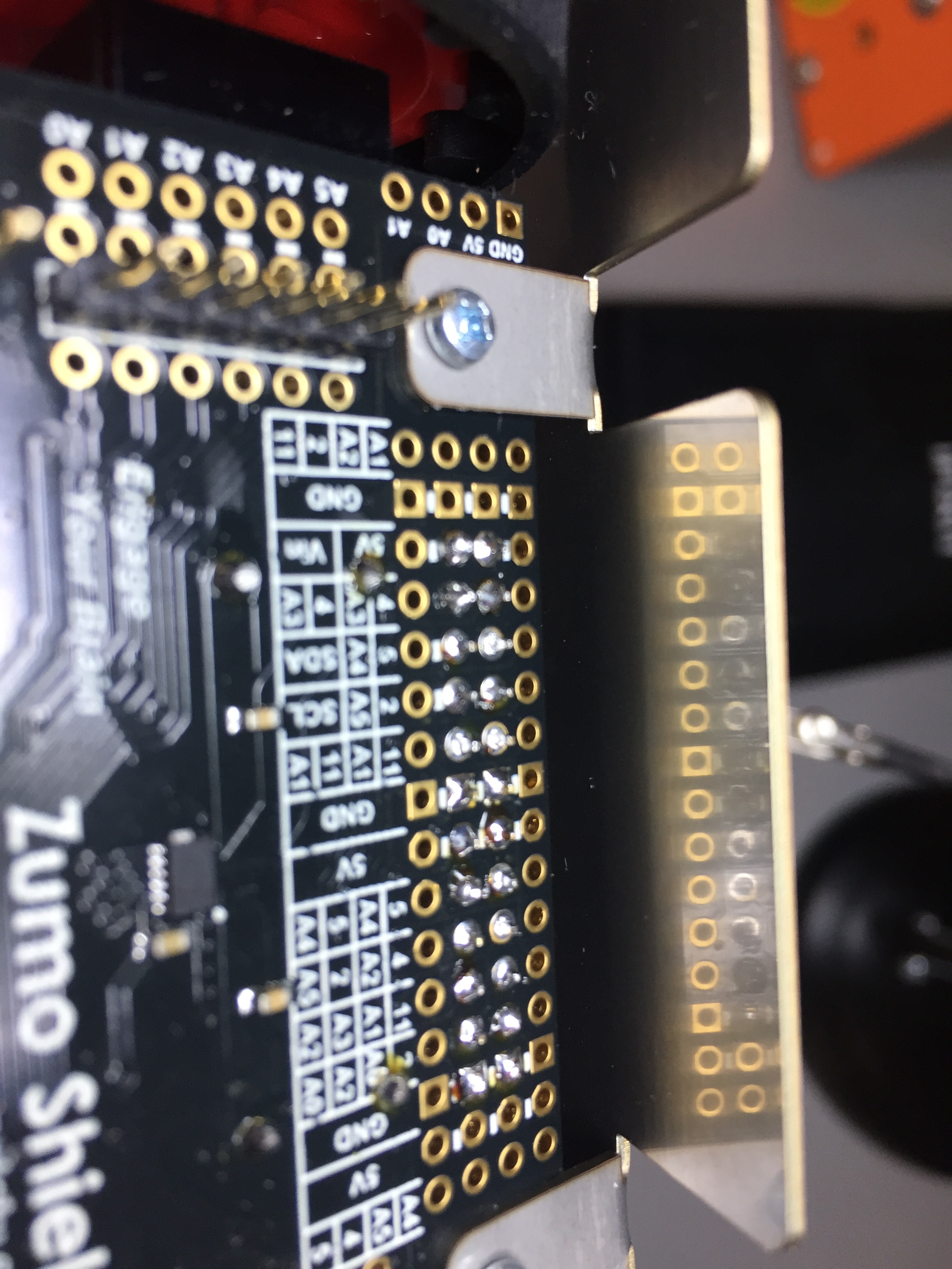
Can you post pictures that clearly show the reflectance sensor array as it is mounted to your Zumo? Can you also post pictures that clearly show the array and shield’s soldered joints?
I have it under battery power only, without the UNO plugged in it shows the vin and ground pins at 7.45V, as soon as I plug the Arduino in it drops to 2.46V
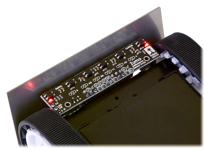
It looks like your Zumo reflectance sensor array is in plugged in the wrong way, which explains the -5V you were measuring (and it seems like you were measuring that voltage across the 5V and GND pins). Connecting power backwards like that is generally a good way to instantaneously damage electronics, but in this case, I suspect your reflectance sensor array and Zumo shield to be okay. Can you try re-orienting your array so that it looks like the following picture and try running the sample code again?