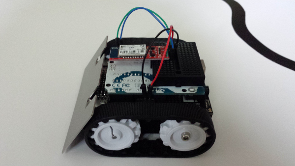
I decided to stick a mini-breadboard to the back of the Uno so that I can put the rear sensor in.
I was also able to add a Bluesmirf bluetooth module to the breadboard so that I can send the robot a signal to stop, so I don’t have to try to catch it or chase it down as I am tuning it, the little bugger is faster than me!
So far I have just been using it with the linefollower sketch as I play around with the PID parameters. I added a section to the main loop that takes a reading every 500ms on the serial port and checks for a ‘s’ and then stops the motors if it finds one. It then waits for a button press to resume following the line. Here is the code I added:
  //first a few variables to use
  char val;
  const int delayTime = 500;
  unsigned long lastTime = 0;

  //then in the setup you must initialize the serial communication at the proper baudrate
  Serial.begin(115200);

  //then this was added to the main loop
  if ((millis() - lastTime) > delayTime)
  {
    if (Serial.available())
    {
      val = Serial.read();
    }
    if (val == 's')
    {
      motors.setSpeeds(0, 0);
      button.waitForButton();
      val = 'x'; //change the value of val arbitrarily so that it doesn't keep reading 's'
    }
    lastTime = millis();
  }
So far it works great and hasn’t seemed to affect the Zumo’s ability to follow the line, although I don’t have it tuned that well yet. The Bluesmirf should come in handy for tuning the front and rear sensors, when I get to those as well.
I posted a pic with the sensors mounted and one with just the Bluesmirf. I am also posting a link to a video I shot with my phone, demonstrating the robot stopping when it receives a ‘s’ and then resuming when the button is pressed. The quality isn’t good, but it is short and you get to see it work.
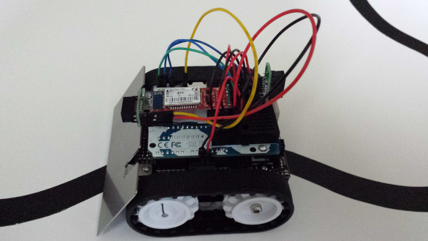
Connect the RX-I to d0 (tx) and TX-0 to d1 (rx), VCC to 5v and GND to gnd on the Uno. Jumper CTS-1 to RTS-0 on the Bluesmirf.
Using Linux it is easy to link to the Bluesmirf if you have a bluetooth module and the bluez stuff installed. First you can run:
hcitool scan
to get the MAC of the Bluesmirf. Then you can bind to it with:
rfcomm bind /dev/rfcomm0 xx:xx:xx:xx:xx:xx
Alternately you can add the MAC to /etc/bluetooth/rfcomm to always be able to connect to it without the above commands.
I use a terminal program called picocom that works well, but any should work. To connect I use:
picocom --b 115200 /dev/rfcomm0
Wait until it says “Terminal Ready” and then you can just type a ‘s’ into the window whenever you want the robot to stop. I’d imagine that it would be just as easy from Windows or other operating systems.
In the video you can see how the Bluesmirf blinks a red led until it is connected, and then it has a green led that stays solidly lit.
I’ve had a lot of fun playing with the Zumo so far!