I am having issues with the QTR threshold on my Zumo robot. I am running the border detection example and can’t find the right threshold level. I am running my Zumo on a tile floor which was working sometimes and picking up the grout and other times not. Figuring that it was an issue with the tile heights I move it to my kitchen table. I put some masking tape down on my wood table and could’t get it to work. It kept on overshooting so I lowered the speed and the threshold (down to 1) like the manual said.
Any ideas? I don’t know how much the material I’m driving on matters or how exactly the IR sensors work. Does it help of the line colors are black or white? I want to get this down before I try to write a line following program.
Hello.
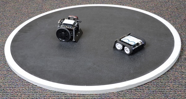
By default, the border detect example is meant for a sumobot ring. The border detect works by looking for a difference in IR reflectance. Standard robot sumo rings are colored black with a white border around the edge.

I think there is not a big enough difference in IR reflectance between the tile and grout or the masking tape and wood table. You might try using black electrical tape to make a ring on the tile and inverting the settings in the code, so the robot tries to look for a black border on a white surface.
If you are trying to test the sensor array, you also might be interested in our new line-following example for the Zumo, which can be found in the “Example projects” section of the user’s guide.
- Jeremy
Thanks Jeremy,
Could you tell me more about the output of the QTR sensor. It seems like you get better IR reflecting off the white than you do the black. Also looking over the code how could I invert the setting in the code. Can the QTR sensor output below 0, if so inverting the settings makes sense? Just trying to figure out how the sensor outputs going from white to black.
Each phototransistor is part of a capacitor discharge circuit that allows a digital I/O line to take an analog reading of the reflected IR by measuring the discharge time of the capacitor. You can find more information on how the sensor works in the QTR-xRC section of the QTR Reflectance Sensor Application Note.
To invert the settings in the code, you can change the if statement checking if the sensor value is less than the QTR_THRESHOLD to greater than.
- Jeremy
Thank you Jeremy.
I got it to work. Instead of using trial and error I was able to input a serial read command into the code. I was able to find the outputs for the electrical tape and the tile. The tile was outputting around 80 and the tape was around 700. I also realized I was forgetting to change the else if statement as well. So when the sensor value is greater than the threshold it works. Thanks you again. This was my first real project and it feels great getting this to work.
I’m glad you figured it out and got it working.
- Jeremy

