Wixelcmd read provides address too high message

Hello,

I have modified the test_adc code to fit what I want to do. Which is trigger on rising edge, then enter DSM mode for a certain period of time to sample input data. I have used test_adc because I would like to print what I am reading. Since I was getting PSEG length and boundary errors when I used arrays of size 32 (3 of them), When I moved them into code space I did not have problem compiling. However, when I tried to load that code into wixel, I got “Invalid data in file” error. As suggested in the forum, I used wixelcmd to see what I read.

I got the following error

wixel-sdk>wixelcmd read apps\test_adc\test_adc.wxl
Address of “input_mode” parameter is too high: 61440.

With no changes to test_adc I get this message, which means it is a good file.

91-1E-D0-87:
input_mode=-1
bar_graph=1
report_period_ms=40

I have used XDATA for the arrays as well which compiled fine but still get the same error.

The size of the wxl file is: 08/24/2015 10:15 PM 25,075 test_adc.wxl

I have not changed any of the makefiles.
Any pointers as to what is going on and how I can fix this problem?

Thanks

Some more data points:

Memory map,

Original test_adc:

Area Addr Size Decimal Bytes (Attributes)


CONST 00001F93 0000010E = 270. bytes (REL,CON,CODE)

  Value  Global                              Global Defined In Module
  -----  --------------------------------   ------------------------
 0C:   00001F93  G$param_input_mode$0$0             test_adc
 0C:   00001F93  _param_input_mode                  test_adc
 0C:   00001F97  G$param_bar_graph$0$0              test_adc

Modified test_adc:
Hexadecimal [32-Bits]

Area Addr Size Decimal Bytes (Attributes)


PSEG 0000F000 000000B2 = 178. bytes (REL,CON,PAG,XDATA)

  Value  Global                              Global Defined In Module
  -----  --------------------------------   ------------------------
 0D:   0000F000  G$param_input_mode$0$0             test_adc
 0D:   0000F000  _param_input_mode                  test_adc
 0D:   0000F004  G$param_bar_graph$0$0              test_adc
 0D:   0000F004  _param_bar_graph                   test_adc

I have tried putting the global variables in different segment using DATA, XDATA and PDATA and none of them seem to work. For example, if I use DATA, the location is 0008 and wixelcmd read complains that it is too low. For anything else, it is too high.

Will changing into a different memory model (medium to huge) will make any difference? In that case, the libraries have to be redone with huge-model as well.

Does the bootloader expects the input parameters to be located at specific addresses? How can I overcome this problem and make it transparent so I dont have to explicitly force data to specific locations.

Thanks

Hi, vgs.

Could you please post the source of your program (either with [code] tags or as an attachment)?

- Kevin

Hi,

I have modifed test_adc.c and couple more files in libraries. Will attach all. One more piece of information that I need to mention is I had moved all new code into test_adc.c without touching any files in libraries dir. However, I had created a new header file to include some essentials in libraries include dir.

Thanks
test_adc.c (20.9 KB)

I need to attach one more…
dma.c (1.98 KB)

board.c
board.c (6.1 KB)

Hello Kevin,

I found this when I googled.

sourceforge.net/p/sdcc/mailman/message/13598342/

As I mentioned, when I dont use XDATA for arrays I got this error

Compiling apps/test_adc/test_adc.rel
Linking apps/test_adc/test_adc.hex

?ASlink-Warning-Paged Area PSEG Length Error

?ASlink-Warning-Paged Area PSEG Boundary Error
make: *** [apps/test_adc/test_adc.hex] Error 1

Then I had to use XDATA or CODE to move the arrays it compiled fine.

Can you please confirm if that is the problem.

Thanks

I haven’t tried compiling or running your program yet, but I took a brief look at your test_adc.c and noticed a few problems.

First of all, it seems like you’re experimenting with the different address space qualifiers (CODE, DATA, PDATA, XDATA) without really understanding what they mean. I would suggest reading over the description of these qualifiers in the Wixel SDK documentation here.

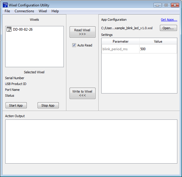
Any variable with a name that starts with “param_” is treated as a Wixel app parameter by the Wixel software, as mentioned in the “Wixel App File Format” section of the Wixel user’s guide. In order for this to work properly, the variable must use the CODE qualifier. That means its value can be changed when (and only when) the app is loaded onto the Wixel. For instance, the example_blink_led app contains a parameter declared like this:

int32 CODE param_blink_period_ms = 500;

When you load this app in the Wixel Configuration Utility, the parameter is configurable on the right:

In your test_adc.c, you’ve removed the CODE qualifier from some parameters (maybe by accident), which means they’re being put in the wrong memory location (in RAM instead of flash memory), and the Wixel SDK can’t make sense of them. So you should change these lines:

int32 param_input_mode = -1;
int32 param_bar_graph = 1;
int32 param_report_period_ms = 40;

back to the way they were in the original test_adc.c:

int32 CODE param_input_mode = 0;
int32 CODE param_bar_graph = 1;
int32 CODE param_report_period_ms = 40;

Putting your adcOutput arrays in code space is the same problem in reverse: it won’t work for what you’re trying to do because they are stored in flash memory and therefore read-only. (Like the SDK documentation says, the CODE qualifier is appropriate for variables and data structures that never need to be changed, like look-up tables.) You should be able to put them in XDATA space instead:

uint16 XDATA adcOutputX[MAX_BUF_SZ] = {0};
uint16 XDATA adcOutputY[MAX_BUF_SZ] = {0};
uint16 XDATA adcOutputZ[MAX_BUF_SZ] = {0};

Could you try making those changes and see if they help?

- Kevin

Thanks Kevin. Really appreciate your help. I don’t remember changing them. It might have happened by mistake. I was not aware of this mechanism of the parameters. Is test_adc covered in users guide? Anyway, I did compile ok with the changes you suggested. Looking at the memory map, I see the address being used is 000022F7. It will take me couple of days to try it out on the device. Will keep you posted.

Regards

The user’s guide doesn’t specifically talk about the test_adc app. However, if you haven’t already, it would be a good idea to look it over for more general information (especially the Wixel App File Format section I mentioned before) and to read the SDK documentation.

- Kevin

Thanks for you help. That fixed the problem. Now I am getting the hang of working with Wixel. However there are few more things that I have to understand.

Moving on to debug the problem. I am using P0 interrupt on rising edge. I picked up code that was posted in the forum which is posted below. If I use this code as is, I loose control over Wixel. However if I remove the last line (EA = 1), things do tend to work as expected. I dont have anything connected to P0 inputs so the interrupt counter seems to indicate no interrupts. Question is how/when to use EA = 1. Since I rely on a whole bunch of printfs to debug my code, I need to be connected to Wixel to gather all data. Also since I use port 0 and timer 1 interrupts and keep one of the interrupt enabled while the other is disabled, I dont want to inadvertently disable interrupts that may cause the wixel to stop responding. Would enabling port 0 interrupt via IEN1 be sufficient or do I have to use EA = 1? Similar question will apply to timer 1 interrupt. Appreciate your help.

[code]void initialize()
{
systemInit();
usbInit();
//setup a falling edge interrupt on P0_1.
PICTL = 0b00001001; //Port 0, inputs 3 to 0 interrupt enable, only for now
//and falling edge interrupt
IEN1 = 0b00100000; //enable port 0 interrupts
EA = 1; //enable all interrupts

}[/code]

Thanks

Hello,

I was able to solve the problem after I changed the code as shown below. The code which is commented out was the original code.

[code]void enablePort0Trigger(void)
{
#if 0
PICTL = (PICTL & ~0b00000001); // Setup Rising edge

PICTL |= 0b00001000; 		//Port 0, inputs 3 to 0 int enable, 
                    		//and rising edge interrupt
IEN1 = 0b00100000;  		//enable port 0 interrupts
//EA = 1;

#endif

P0IE = 0;         // Disable the P0 interrupt while we are reconfiguring it (maybe not necessary).
__asm nop __endasm; __asm nop __endasm; __asm nop __endasm;

PICTL |= (1<<3);  // PICTL.P0IENL = 1  Enable the Port 0 interrupts for inputs 0-3 (USB_RESUME is #7).
PICTL &= ~(1<<0); // PICTL.P0ICON = 0  Detect rising edges (this is required for waking up).
P0IE = 1;         // IEN1: Enable P0 int POIE is bit 5 (port 0 int enable)
__asm nop __endasm; __asm nop __endasm; __asm nop __endasm;
EA = 1;	      // IEN0: Each int source is individually enabled/disabled

}[/code]

For now, wixel responds normally to all the commands from wixel configuration tool.

Again, Thanks for all the help.

Regards

I’m glad to hear you’re getting things working. By the way, if you want to post source code in the future, it’s easier to read if you put it inside [code][/code] tags.

- Kevin

Hello,

I’m back again with the same problem. The printfs dont show up. I have modified test_adc. The possible conflict I see is with usbComService() which uses Port 0 and port 0 interrupt. The strange thing is even if I comment out ADC, DMA, DSM etc, I still dont get printfs. However, when param_input_mode = -1, I do get printfs even though the path is similar.

If usbComService is using port 0, can I move to other port for example, P1 or P2 and be able to get the printfs?

Here is a summary of what I’m doing.

selecting Port0 (0,1,2) as peripheral input ports since I’m using analog inputs as I am using adxl377. One question I have here is will configuring those ports (0,1,2) as GPIO with pu/pd as done by test_adc can read analog signals?
Configuring rest of the unused ports as output ports as per the datasheet pg. 87.
Initialize, ADC,DMA,DSM(Timer1).
Enabling port0 interrupt and triggering on rising edge.
When I get P0 interrupt, I disable P0 and enable DSM for about 50ms to sample input data.
After 50 ms I disable DSM(Timer1 interrupt) and enable P0 interrupt.

I have attached the source code.

Regards
newcode.c (20.3 KB)

Hello.

Yes, you can still take analog readings on pins of the CC2511F32 that have pull-ups or pull-downs enabled. The test_adc app shows how to do that.

It sounds like you are seeing no output in your terminal program from the Wixel when param_input_mode is a value other than -1. You should first figure out if you are even calling printf. Your code won’t call printf if timer1Count is 0, so you might try adding a call to printf on line 587 that prints the value of timer1Count. Another issue you might have is that you are trying to print the VT100 command for “go to 0,0” multiple times in the same report, which means that later parts of your report could override earlier parts. You should only print that command once at the beginning of each report.

–David

Thanks David! The problem turned out to have to do with the MAX_BUF_SZ and printing the graph. I was using 128 words. Add to that, the graphs which may have flooded the USB interface and cause all kinds of problems including usb interface going down and windows would print that usb is not responding. Commenting out most of the code still caused the same behavior. But bringing down the buffer size to 8 has stabilized things greatly so I can proceed further.

Thanks for point out the 0,0 location thing. Should I change the input ports to P2_1,2,3? I can do that if P0 has conflicts with USB realated code. Since I dont have other debug mechanisms, I have to rely heavily on printfs. In addition to LEDs and printfs, can I use other methods?

Regards

Sorry, here I go again.

When I went back to the data sheet, this is what I found on page 91

When using the ADC in an application, some or all of the P0 pins must be configured as
ADC inputs. The port pins are mapped to the ADC inputs so that P0_7 – P0_0 corresponds
to AIN7 - AIN0. To configure a P0 pin to be used as an ADC input the corresponding bit in
the ADCCFG register must be set to 1. The default values in this register select the Port 0
pins as non-ADC input i.e. digital input/outputs.

The settings in the ADCCFG register override the settings in P0SEL (the register used to
select a pin to be either GPIO or to have a peripheral function).

With this information from the data sheet, it appears that I have to use the P0 ports as peripheral ports. However, page 103 says:

Trigger on rising edge. P0SEL.SELP0_1 and P0DIR.P0_1 must be 0

So it appears that this may not fit my plans of using P0 pins as GPIO and trigger on rising edge and then start ADC conversion because ADCCFG will override P0SEL.

What can be done to trigger on rising edge on port 0 input and still use those ports as ADC ports?

My thoughts are to setup port 0 as GPIO input ports, after a rising edge P0 interrupt, (within the interrupt) change the configuration of P0 ports to peripheral since ADCCFG overrides P0SEL. Go through ADC conversion and revert back the P0 ports to GPIO input waiting for the next P0 interrupt.

Right now, as soon as I enable P0 rising edge trigger, I get stuck somewhere with the LED solid green. I am toggling redled if I get an interrupt but I dont think I am getting an interrupt. If I dont enable P0 rising edge trigger, everything is normal.

Thanks for your help.

I should have said this in my previous post, but the USB code for the Wixel does not use Port 0. Why do you think the USB code conflicts with Port 0? All of the pins on Port 2 are already being used for something else on the Wixel, so I do not recommend using them unless there is a good reason. For example P2_3 is used to detect when power is supplied to VIN.

I have not tried to use a single Wixel pin to generate interrupts and perform ADC conversions. If configuring it as an ADC pin prevents the interrupts from working, you might try leaving the pin configured for interrupts most of the time, and then temporarily configuring it as an ADC pin whenever you need to take a reading.

Alternatively, you might try wiring the analog signal to two different pins, and using one of the pins for interrupts while using the other pin for analog-to-digital conversion.

–David

Thanks David. Since I read this in the data sheet, and I found the code listed below, I thought there was some dependency even though it said bit 7.

P0ICON 0 R/W Port 0, inputs 7 to 0 interrupt configuration. This bit selects the interrupt request condition for all port 0 inputs. For CC2511Fx, this bit must be set to 0 when USB is used, since the internal USB resume interrupt mapped to P0[7] uses rising edge.

if (P0IFG & 0x80)
    {
	usbSuspendMode = 0;
    }

Thanks for confirming that. My thought was to configure pins 0,1,2 as GPIO to trap rising edge. Then from within the interrupt, switch to peripheral and get the reading and switch it back. Hopefully I can do that.

The biggest problem I’m facing now is as soon as I enable either P0 or T1 interrupts, the prints stop working. I did separate the two so that I can get each one working independently. I have followed the examples provided in other APPS but that is not working. I feel that when there is an interrupt, either the ISR in the vector table is invalid or configuring the registers exposes some bug in printf which stops printing. It sounds wierd. If someone would like to share examples of how to go about defining ISRs or providing other pointers will really help.

Regards

Okay, I see now that there is some code in the usbSleep function in the Wixel SDK that modifies P0IE and PICTL, because those registers are needed to allow the Wixel to wake up from suspend mode. If you simply avoid calling usbSleep in your application, you should not have to worry about that.

If you want help debugging your problem with the P0 and T1 interrupts causing printf to stop working, I suggest that you simplify your code as much as possible and post it here. For example, since either interrupt causes the problem, then you can pick whichever interrupt is simpler to use and remove all the code for the other one. You should remove all commented-out code and any code that isn’t strictly necessary for showing the problem. The program should be runnable on an ordinary Wixel with no other hardware. You should say what the expected output is and what the actual output is. If you post this information, I can take a look at it and I might have some advice.

–David